Monday, January 26, 2015
Build a Peak Indicator
When when the condition of point is greater then how much + 4dB, changes for encouraged D1. Its handy around each one siphon with games console with good, around very last amplifiers and also in the alternative use, so that you can most people wanted. Together with the selling prices with outlet, a signify takes place by using concentrations previously + five dB (1. 25V rms). To get adapting to it within amounts of point, we will employ a more trim, in advance of capacitor C1.
Peak Indicator Circuit Diagram :
R1 = 10K
R2 = 1.2K
R3 = 220K
R4 = 4.7K
R5 = 4.7K
C1 = 47uF-25V
C2 = 2.2uF-25V
Q1 = BC550C
Q2 = BC550C
D1 = Red LED
Notes:
- It can be assembled on a general purpose PCB.
- It can be powered from a 12V-15V regulated power supply.
Thursday, November 20, 2014
PWM Controler With Ic 555

IC Timer 555 has a basic PWM controller with pulse width control feature 0 .. 100% which is controlled using the R1, at the time of controlling the oscillator frequency relatively stabi so it may be used to build the Simple PWM controller. Frequency of Simple PWM controller 555 depending on the value of R1 and C1, values shown R1 and C1 will form the output with a frequency of 170 to 200 Hz. Diode-diode used in the Simple PWM controller With this 555 can use a 1N4148.R2, R3 and C3 form a giver triger circuit beginning at the reset IC 555 for 2 seconds. If you want to use a series of Simple PWM controller 555 with the V + not +12 V, it does not matter to raise R2 where (V + * R2) / (R2 + R3) is about 2, because it limits the signal level reset is 0.5 .. 1V. If you do not do that, then signal the kickstart to get too close to the limit reset signal reception.
Q output of 555 on the Simple PWM controller circuit 555 is used for driver PWM pulse, so that the discharge pin is used for transistor output driver instead. This is an open collector output, and is used as an active signal is low, so it can work. D3 protects the output transistor of the load induction. You may replace any suitable transistors for Q1, BD140 is 1.5 amps.
C4 and C5 is the power decoupling capacitor for the IC 555 on the Simple PWM controller circuit 555, which produce relatively large level of push-pull output stage.
Control Relay Circuit with 9 Second
See figure below its Control Relay Circuit Schematics.

Wednesday, November 19, 2014
45 W Stereo Tube Amplifier
Stereo Amplifier with Tube
Stereo amplifier is very simple, consisting of 5 active components including the power supply it. Series Stereo Amplifier With Tube was prepared with 5 units trioda tube consisting of 1 unit tubes 5Y3 GT vacuum rectifier, 2 tube tube trioda 6SF5 GT high-mu tube 6k6 and 2 units which form the power beam amplifiers.
Power consumption for the circuit with a tube stereo amplifier is not more than 45 Watt. Current consumption for the circuit with a tube stereo amplifier is around 3A. A complete range of stereo amplifiers with this tube can be seen from the following series of images.
Stereo Amplifier With Tube

Sign Component Stereo Amplifier With Tube
- R1, R10, R13 2.2M
- R2 470K 1/2W
- 1 Meg 1/2W R3
- R4 220K 1/2W
- R5 330 Ohm 2W
- R6 220K 1/2W
- R7 2.2Meg 1/2W
- R8 1Meg 1/2W
- R9 720 Ohm 20W
- R11 33K 1/2W
- R12 22K 1/2W
- C1, C9 400V 0.005uF
- C2 0.05uF 600V
- C3 20uF 25V
- C4 0.01uF 400V
- C5 200uuF 400V
- C6, C7 15uF 450V
- C8 15uF 400V
- T1 117V Primary, Secondary 350VCT, 2 × 6.3V
- T2 7600 Ohm Primary, Secondary 4 or 8 Ohm
- SW1 SPST Switch
- SP1, SP2 12 "4 / 8 ohm
- C8 in the series stereo tube amplifier with the above serves to reduce radio frequency interference and to optimize the work of a wild series of ampifier stereo with these tubes.
Discharge the large electrolytic capacitor load
If the switching regulator fails to work or fail to start, then it is usually of the electrolytic capacitor is storing charge. There are habits of some engineers dumping electrolyte capacitor like this using solder. This is actually a poor habit. Because without them knowing things like this sometimes can lead to broken solder element.

 Note that the voltage on the electric charge of the electrolyte capacitor is 300V. While working voltage 220v only solder element. If the charge on the electrolytic capacitors are still full and the 220u electrolytic capacitors or more then this electric charge can only damage the solder element.
Read More..
Why this may happen?
Another bad habit of throwing of the electrolytic capacitor is to download shortkan legs electrolyte capacitor with a screwdriver. It is no possibility of damaging electrolytic capacitor itself, in which connection leg electrolyte capacitor is no risk in it will burn.
How should the dumping of the electrolytic capacitors?
- Always provide a resistor with a value of about 30k ~ 50k/2w
- If the correct power supply to the problem fails to work, then the resistor is normally for a while we solder directly on the legs of of the electrolytic capacitor. And if the problem is ok, the new resistor is removed.
Stereophonic Amplifier with TDA7088T
There are two signals that are directed at the so-called FM transmitterthe coder (coding). Multiplexing Mpx signal has been contained, two left signals and right indirectly. Frequency modulation of a transmitter carried by the signal Mpx. The receiver output signal is obtained on Mpx and FM detector is then passed to the decoder. At the decoder do the opposite with the coder in the transmitter, because at this level produced two signals L and D.
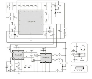
Signal is amplified by audio amplifier dientik two, then reproduced through two speakers are the same. Now listeners can heard coming from the left half the loudspeaker is placed on the left and right half of which is placed on the right side. Situation amid the orchestra will be equal to that of the second lordspeaker reproduced, made an impression on the listener as if there.
The third loudspeaker placed midway between the left and right. Based on all these listeners have a picture of the layout space, which is significantly increased total musical impression. Electronic circuits of the portable stereophonic radio receiver with headphones reproduction, made by the IC TDA 7088T is shown in Figure the above. This is a practical embodiment of the receiver with TDA7040T decoder and two audio amplifier with TDA7050T IC.
Choke (coils) L3, L4 and L5 are HF coil allows the headphone cable is used as a receiving antenna. this fulfilled by connecting one contact of the plug-in headphones, through a 10 pF capacitor at the point where the output of the antenna is connected. Coil has a significant barrier to the signal station, preventing ground connection through capacitor 47 mF or through the TDA7050T output.
Tuesday, November 18, 2014
Driver On Line Follower Robot
Motor Drive On Line Follower Robot - To move the Line Follower 2 options can be used, namely motor or DC motor servo motor. If you want to use a DC motor, it must use a DC motor is mounted gear system (geared motors DC).Kind of like it is still difficult to find in the market, so the choice often falls to the servo motor.Another advantage of the servo motor is a servo motor can be controlled directly from the microcontroller PIC16F84 with no extra-Driver IC again.
| Motor Drive On Line Follower Robot |
Wheel Drive On Line Follower Robot - Wheels are used in line follower may vary - kinds, ranging from the brand, type, dimensions, and so forth. Line Follower Robot are generally categorized based on the number of wheels it has.Starting from the robot with two wheels, three wheels or four wheels. But that is commonly used is a robot with three or four wheels.
| Wheel Drive On Line Follower Robot |
Placed behind a pair of wheels connected by two motors each - each have an independent pace.It is important that the robot can turn left and to right and set the desired rotation rounds. While the front wheels could use a caster wheel that serves as a buffer. Many brands of caster wheels that can be used, one of the most famous is from the manufacturer Tamiya. However, no cane akarpun so - if we want a cheaper and sometimes free, odor-preventing former rodadeodorant can used as a caster wheel.
In the Line Follower Robot Microcontroller Many types of microcontrollers that can be used in line follower robot, some examples include AT89C2051 (8051 Core), AT89C51 (8051 Core), ATmega8 (AVR Core), ATmega16 (AVR Core) and many more.
In the microcontroller, the program will be included so that the robot can adjust the rotation speed of each motor and able to perform the desired movement. Because the line follower robot speed is high enough, then some of the control algorithm needs to be applied to a robot capable of running smoothly. Control that can be a continuous control, PID, fuzzy logic, or the other.
Speed setting is important, especially when faced with change of trajectory, from a straight trajectory to bend or otherwise of the bend to the straight path. Just as when the robot moves fast and then find a corner, then the robot would be bounced. That requires a series of dynamic motor speed control depending on the type of trajectory is traversed. If the robot goes straight, the speed of the robot cultivated at a maximum. If the condition of the bend, then the speed is reduced depends on the sharpness of the bend. In essence, the speed of the robot is made flexible according to the situation on the ground. On the robot, the speed reduction can be done using the PWM (Pulse widht Modulation) controller, namely the reduction of speed by reducing the current to the motor.
Subscribe to:
Posts (Atom)