Thursday, November 20, 2014

PWM Controler With Ic 555


IC Timer 555 has a basic PWM controller with pulse width control feature 0 .. 100% which is controlled using the R1, at the time of controlling the oscillator frequency relatively stabi so it may be used to build the Simple PWM controller. Frequency of Simple PWM controller 555 depending on the value of R1 and C1, values ​​shown R1 and C1 will form the output with a frequency of 170 to 200 Hz. Diode-diode used in the Simple PWM controller With this 555 can use a 1N4148.R2, R3 and C3 form a giver triger circuit beginning at the reset IC 555 for 2 seconds. If you want to use a series of Simple PWM controller 555 with the V + not +12 V, it does not matter to raise  R2 where (V + * R2) / (R2 + R3) is about 2, because it limits the signal level reset is 0.5 .. 1V. If you do not do that, then signal the kickstart to get too close to the limit reset signal reception.

Q output of 555 on the Simple PWM controller circuit 555 is used for driver PWM pulse, so that the discharge pin is used for transistor output driver instead. This is an open collector output, and is used as an active signal is low, so it can work. D3 protects the output transistor of the load induction. You may replace any suitable transistors for Q1, BD140 is 1.5 amps.

C4 and C5 is the power decoupling capacitor for the IC 555 on the Simple PWM controller circuit 555, which produce relatively large level of push-pull output stage.

Read More..

Control Relay Circuit with 9 Second

See figure below its Control Relay Circuit Schematics.

Control
Read More..

Wednesday, November 19, 2014

45 W Stereo Tube Amplifier

Stereo Amplifier with Tube
Stereo amplifier is very simple, consisting of 5 active components including the power supply it. Series Stereo Amplifier With Tube was prepared with 5 units trioda tube consisting of 1 unit tubes 5Y3 GT vacuum rectifier, 2 tube tube trioda 6SF5 GT high-mu tube 6k6 and 2 units which form the power beam amplifiers.


Power consumption for the circuit with a tube stereo amplifier is not more than 45 Watt. Current consumption for the circuit with a tube stereo amplifier is around 3A. A complete range of stereo amplifiers with this tube can be seen from the following series of images.

Stereo Amplifier With Tube


Sign Component Stereo Amplifier With Tube
  • R1, R10, R13 2.2M
  • R2 470K 1/2W
  • 1 Meg 1/2W R3
  • R4 220K 1/2W
  • R5 330 Ohm 2W
  • R6 220K 1/2W
  • R7 2.2Meg 1/2W
  • R8 1Meg 1/2W
  • R9 720 Ohm 20W
  • R11 33K 1/2W
  • R12 22K 1/2W
  • C1, C9 400V 0.005uF
  • C2 0.05uF 600V
  • C3 20uF 25V
  • C4 0.01uF 400V
  • C5 200uuF 400V
  • C6, C7 15uF 450V
  • C8 15uF 400V
  • T1 117V Primary, Secondary 350VCT, 2 × 6.3V
  • T2 7600 Ohm Primary, Secondary 4 or 8 Ohm
  • SW1 SPST Switch
  • SP1, SP2 12 "4 / 8 ohm
  • C8 in the series stereo tube amplifier with the above serves to reduce radio frequency interference and to optimize the work of a wild series of ampifier stereo with these tubes.
Read More..

Discharge the large electrolytic capacitor load

If the switching regulator fails to work or fail to start, then it is usually of the electrolytic capacitor is storing charge. There are habits of some engineers dumping electrolyte capacitor like this using solder. This is actually a poor habit. Because without them knowing things like this sometimes can lead to broken solder element.

Why this may happen?
Note that the voltage on the electric charge of the electrolyte capacitor is 300V. While working voltage 220v only solder element. If the charge on the electrolytic capacitors are still full and the 220u electrolytic capacitors or more then this electric charge can only damage the solder element.

Another bad habit of throwing of the electrolytic capacitor is to download shortkan legs electrolyte capacitor with a screwdriver. It is no possibility of damaging electrolytic capacitor itself, in which connection leg electrolyte capacitor is no risk in it will burn.

How should the dumping of the electrolytic capacitors?
  • Always provide a resistor with a value of about 30k ~ 50k/2w
  • If the correct power supply to the problem fails to work, then the resistor is normally for a while we solder directly on the legs of of the electrolytic capacitor. And if the problem is ok, the new resistor is removed.
Read More..

Stereophonic Amplifier with TDA7088T

There are two signals that are directed at the so-called FM transmitterthe coder (coding). Multiplexing Mpx signal has been contained, two left signals and right indirectly. Frequency modulation of a transmitter carried by the signal Mpx. The receiver output signal is obtained on Mpx and FM detector is then passed to the decoder. At the decoder do the opposite with the coder in the transmitter, because at this level produced two signals L and D.
ic
Signal is amplified by audio amplifier dientik two, then reproduced through two speakers are the same. Now listeners can heard coming from the left half the loudspeaker is placed on the left and right half of which is placed on the right side. Situation amid the orchestra will be equal to that of the second lordspeaker reproduced, made ​​an impression on the listener as if there.

The third loudspeaker placed midway between the left and right. Based on all these listeners have a picture of the layout space, which is significantly increased total musical impression. Electronic circuits of the portable stereophonic radio receiver with headphones reproduction, made ​​by the IC TDA 7088T is shown in Figure the above. This is a practical embodiment of the receiver with TDA7040T decoder and two audio amplifier with TDA7050T IC.

Choke (coils) L3, L4 and L5 are HF coil allows the headphone cable is used as a receiving antenna. this fulfilled by connecting one contact of the plug-in headphones, through a 10 pF capacitor at the point where the output of the antenna is connected. Coil has a significant barrier to the signal station, preventing ground connection through capacitor 47 mF or through the TDA7050T output.
Read More..

Tuesday, November 18, 2014

Driver On Line Follower Robot

Motor Drive On Line Follower Robot - To move the Line Follower 2 options can be used, namely motor or DC motor servo motor. If you want to use a DC motor, it must use a DC motor is mounted gear system (geared motors DC).Kind of like it is still difficult to find in the market, so the choice often falls to the servo motor.Another advantage of the servo motor is a servo motor can be controlled directly from the microcontroller PIC16F84 with no extra-Driver IC again.

Motor Drive On Line Follower Robot
Wheel Drive On Line Follower Robot - Wheels are used in line follower may vary - kinds, ranging from the brand, type, dimensions, and so forth. Line Follower Robot are generally categorized based on the number of wheels it has.Starting from the robot with two wheels, three wheels or four wheels. But that is commonly used is a robot with three or four wheels.

Wheel Drive On Line Follower Robot 

Placed behind a pair of wheels connected by two motors each - each have an independent pace.It is important that the robot can turn left and to right and set the desired rotation rounds. While the front wheels could use a caster wheel that serves as a buffer. Many brands of caster wheels that can be used, one of the most famous is from the manufacturer Tamiya. However, no cane akarpun so - if we want a cheaper and sometimes free, odor-preventing former rodadeodorant can used as a caster wheel.

In the Line Follower Robot Microcontroller Many types of microcontrollers that can be used in line follower robot, some examples include AT89C2051 (8051 Core), AT89C51 (8051 Core), ATmega8 (AVR Core), ATmega16 (AVR Core) and many more.

In the microcontroller, the program will be included so that the robot can adjust the rotation speed of each motor and able to perform the desired movement. Because the line follower robot speed is high enough, then some of the control algorithm needs to be applied to a robot capable of running smoothly. Control that can be a continuous control, PID, fuzzy logic, or the other.

Speed setting is important, especially when faced with change of trajectory, from a straight trajectory to bend or otherwise of the bend to the straight path. Just as when the robot moves fast and then find a corner, then the robot would be bounced. That requires a series of dynamic motor speed control depending on the type of trajectory is traversed. If the robot goes straight, the speed of the robot cultivated at a maximum. If the condition of the bend, then the speed is reduced depends on the sharpness of the bend. In essence, the speed of the robot is made flexible according to the situation on the ground. On the robot, the speed reduction can be done using the PWM (Pulse widht Modulation) controller, namely the reduction of speed by reducing the current to the motor.
Read More..

IC LA78040 schematic for vertical deflection

Synchronization circuit to make the signals useful in the process of scanning of the transmitter and sent to the Vertical and Horizontal. To be able to produce images on the picture tube phosphor surface is the same as what was sent, then the necessary adjustments to correct with ualsan which has decomposed on the sender and receiver on the review must be made ​​again, and this is called synchronization.

Click to view larger


On TV transmitter switching pulses that have made ​​the same frequency as in the reviewing, and by using the switching pulse is then mulapenguilasan point getter on the tube and picture tube can be adjusted simultaneously. 
At the transmitter, each end of the line reviews one pulse is emitted horizontally, and also at each end of the line vertical review (this is called a field review), another pulse is emitted. At the receiver using switching pulses had the time of the beginning (start) review can be arranged horizontally and vertically. Switching pulses are called the horizontal synchronizing signal and vertical synchronization.Vertical SynchronizationA. Vertical in the tv series has the following functionsa) bend / open beams of light (information) to the vertical direction.b) Synchronize files from a transmitter in the form of images with short time.
Read More..

DC DC Converter 12V to 24V

This simple circuit is a DC-DC converter that converting up 12V source to a 24V. It can be used to run radios, small lights, relays, horns and other 24V accessories from a 12V vehicle with a maximum draw of about 800mA.


This DC-DC Converter can be used to charge one 12V battery from another, or step up the voltage just enough to provide necessary overhead for a 12V linear regulator. Using one op-amp as a squarewave oscillator to ring an inductor and another op-amp in a feedback loop, it wont drift around under varying loads, providing a stable 24V source for many applications. With a wide adjustment in output this circuit has many uses. 

Parts List
R1-R4,R7-R8 100K 1/4W Resistor 
R5 470 Ohm 1/2W Resistor 
R6 10K Linear Pot 
C1 0.01uF Mylar Capacitor 
C2 0.1uF Ceramic Disc Capacitor 
C3 470uF 63V Electrolytic Capacitor 
D1 1N4004 Rectifier Diode 
D2 BY229-400 Fast Recovery Diode See Notes
Q1 BC337 NPN Power Transistor 
U1 LM358 Dual Op Amp IC 
L1 See Notes 
MISC Board, Wire, Socket For U1, Case, Knob For R6, Heatsink for Q1

DC- DC Converter Notes 
1. R6 sets the output voltage. This can be calculated by Vout = 12 x (R8/(R8+R7)) x (R6B/R6A). 
2. L1 is made by winding 60 turns of 0.63MM magnet wire on a toroidial core measuring 15MM (OD) by 8MM (ID) by 6MM (H). 
3. D2 can be any fast recovery diode rated at greater then 100V at 5A. It is very important that the diode be fast recovery and not a standard rectifier.4. Q1 will need a heatsink.
Read More..

Monday, November 17, 2014

Power Supply EL 34

Power supply for EL-34 tube is specially designed for the purposes of power supply at the push-pull amplifier with EL-34 tube as in article 35 Watt Tube Power Amplifier Push Pull before. Power supply for EL-34 tube amplifier is made with transformers CT and 2 pieces diode as rectifier. Mechanical filters are applied in the power supply uses 3 levels. Power supply for tube power amplifier can deliver output voltages +220 VDC. Circuit details can be seen in the following figure.


The above power supply circuit has a high output voltage so that need to be considered in the manufacture and perakitanya because electricity can tesengat (stun). Power Supply For Tube Power Amplifier With Diode EL-34 was created specifically for the power amplifier tube push pull EL-34.
Read More..

Police Siren Circuit

This is image of police siren circuit, this siren series can be applied in motorcycle or car. Electronic components used are 2 pcs NE555 IC as an stable multivibrators. Frequency of police sirens are controlled by IC NE555 Pin no.5.

Police Siren circuit components:

IC NEE555 = 2 pieces
2.2 KOhm Resistor = 2 pieces
Resistors 47KOhm = 1 piece
Capacitors .01 UF = 1 piece
Kapsitor 47 UF = 1 piece
Kapsitor 0.1 UF = 1 piece
Capacitors 1 uF/16V = 1 pc
Potentiometer 47 KOhm = 1 piece
Potentiometer 100 KOhm = 1 piece
Speaker = 1 piece
Micro Switch = 1 piece
Power Supply 5V - 15V
Read More..

12V to 20V DC converter

DC To DC Converter circuit used to be an alter tegngan voltage DC to DC with different concepts. DC to DC converter circuit +12 V to + /-20V is working to change the battery voltage from 12V DC to 20V DC voltage symmetrical. DC to DC converter circuit is often applied to the power amplifier udio on car audio systems. DC to DC converter circuit uses a TL494 IC as power plsa for the converter. TL494 IC is a PWM controller with an adjustable frequency from 40-60Hz through a potentiometer. Then from the TL494 PWM signal is given to the driver MOSFET inverter TPS2811P to be given to the power inverter with 2 units of MOSFET transistors. Circuit details can be seen in the figure following the DC to DC converter.

DC To DC converter circuit +12 V To + / - 20V

+12V

List Components DC To DC Converter +12 V To + / - 20V
R1, R2 = 10
R3, R4, R6, R7 = 1k
R5 = 22k
R8 = 4.7k
R9 = 100k
C1, C2 = 10000uF
C3, C6 = 47 u
C4 = 10U
C5, C7, C14 = 100n
C8, C9 = 4700u
C12 = 1N
C13 = 2.2u
U1 = TL494
U2 = TPS2811P
Q1, Q2 = FDB045AN
D1-D4 = 1N5822
D5 = 1N4148
FU1 = 10A
L1 = 10U
L2 = ferrite BEAD
RV1 = 2.2k
RV2 = 24k
T1 = TRAN-3P3S
DC To DC converter circuit +12 V To + / - 20V is capable of supplying up to 100W and can power supplying currents up to 3A. In making DC To DC Converter +12 V To + / - 20V has to be careful and cautious because there are parts of DC To DC Converter +12 V To + / - 20V in the form of an AC circuit.
Read More..

Sunday, November 16, 2014

Digital Thermometer 0 100 0°Celsius

Digital Thermometer 0-100.0 ° C is a digital thermometer that operates in mode temperature measurement in Celsius (° C). Digital Thermometer 0-100.0 ° C in this article using the form data processing microcontroller AT89C4051.
Temperature sensors used in Digital Thermometer 0-100.0 ° C. This temperature sensor LM35D. Digital Thermometer 0-100.0 ° C. It uses the temperature measurement data viewer in the form of 1 line LCD viewer. Digital Thermometer 0-100.0 ° C. It can display the temperature measurement data with a resolution of 0.1 ° C.
Digital Thermometer 0-100.0 ° C 


Digital Thermometer 0-100.0 ° C. These temperature sensors make use of LM35D as temperature sensing. In Digital Thermometer 0-100.0 ° C. This temperature sensor measurement data this LM35D (Level Voltage) is then converted into 4-bit binary data using the ADC CA3162. Then the 4-bit data from ADC CA3162 which is a measurement of data if the temperature is in the AT89C4951 microcontroller so that it becomes an operating principle of temperature measurement based on digital thermometers. In the final stage of the Digital Thermometer 0-100.0 ° C. These data digitla adlah appearance temperature measurement, using digital data viewer of the LCD 1 line.
Read More..

Saturday, November 15, 2014

SEVEN SEGMENT INTRUDER ALARM CIRCUIT

Here is the circuit diagram of a seven segment counter based on the counter IC CD 4033. This circuit can be used in conjunction with various circuits where a counter to display the progress  adds some more attraction. IC NE 555 is wired as an astable multivibrator for triggering the CD 4033. For each pulse the out put of CD 4033 advances by one count.The output of CD 4033 is displayed by the seven segment LED display LT543. Switch S1 is used to initiate the counting. Diode D1 prevents the risk of accidental polarity reversal.

Seven Segment Circuit Diagram with Parts List


Read More..

Friday, November 14, 2014

PWM LAMP DIMMER

A simple and efficient PWM lamp dimmer using timer IC NE555 is discussed in this article. Earlier linear regulator based dimmers can only attain a maximum efficiency of 50% and are far inferior when compared to the PWM based dimmers which can hit well over 90% efficiency. Since less amount of power is wasted as heat, the switching elements of PWM dimmers require a smaller heat sink and this saves a lot of size and weight. In simple words, the most outstanding features of the PWM based lamp dimmers are high efficiency and low physical size. The circuit diagram of a 12V PWM lamp dimmer is shown below.


Fig. 1
As you can see, NE555 timer IC which is wired as an astable multivibrator operating at 2.8KHz forms the heart of this circuit. Resistors R1, R2, POT R3 and capacitor C1 are the timing components. Duty cycle of the IC’s output can be adjusted using the POT R3. higher the duty cycle means higher the lamp brightness and lower the duty cycle means lower the lamp brightness. Diode D1 by-passes the lower half of the POT R3 during the charging cycle of the astable multivibrator. This is done in order to keep the output frequency constant irrespective of the duty cycle. Transistors Q1 and Q2 forms a darlington driver stage for the 12V lamp. Resistor R4 limits the base current of transistor Q1.

Understanding the variable duty cycle astable multivibrator

As I have said earlier, the variable duty cycle astable multi vibrator based on NE555 forms the foundation of this circuit and a good knowledge on it is essential for designing projects like this. For the ease of explanation the timing side of the astable multivibrator is redrawn in the figure below.
Fig. 2

Upper and lower halves of the POT R3 are denoted as Rx and Ry respectively. Consider the output of the astable multivibrator to be high at the starting instant. Now the capacitor C1 charges through the path R1, Rx, and R2. The lower half of POT R3 i.e. Ry is out of the scene because the diode D1 by-passes it. When the voltage across the capacitor reaches 2/3 Vcc, the internal upper comparator flips its output which makes the internal flip flop to toggle its output. As a result the output of the astable multivibrator goes low. In simple words, the output of the astable multivibrator remains high until the charge across C1 becomes equal to 2/3 Vcc and here it is according to the equation Ton = 0.67(R1+Rx+R2)C1.

Since the internal flip flop is set now, the capacitor starts discharging through the path R2, Ry into the discharge pin. When the voltage across the capacitor C1 becomes 1/3 Vcc, the lower comparator flips its output and this in turn makes the internal flip flop to toggle its output again. 

This makes the output of the astable multivibrator high. To be simple, the output of the astable multivibrator remains low until the voltage across the capacitor C1 becomes 1/3 Vcc and it is according to the equation Toff = 0.67(R2+Ry)C1. Have a look at the internal block diagram of NE555 timer shown below for better understanding.
Fig. 3

How does the frequency remain constant irrespective of the position of POT3 knob?

What ever may be the position of  POT3 knob, the total resistance across it remains the same (50K here). If anything decreases in the upper side (Rx) the same amount will be increased in the lower (Ry) and the same thing gets applied to the higher(Ton) and lower(Toff) time periods. The derivation shown below will help you to grasp the matter easily.

With reference to Fig 2, we have:

Ton = 0.67(R1+Rx+R2)C1
Toff = 0.67(R2+Ry)C1

Total time period of the output waveform “T” is according to the equation :
T = Ton + Toff

Therefore, T = 0.67(R1+Rx+R2+R2+Ry)C1
           T= 0.67(R1+2R2+Rx+Ry)C1

We know that Rx + Ry  = R3

Therefore, T = 0.67(R1+2R2+R3)C1

Therefore, frequency F = 1/(0.67(R1+2R2+R3)C1) 

From the above equation its is clear that the frequency depends only on the value of the components C1, R1, R2  and the over all value of R3 and it has nothing to do with the position of R3 knob.

Read More..

TDA1554 22W Stereo Amplifier Diagram Circuit

Here is the 22 watt stereo audio power amplifier circuit diagram based on TDA1554 and integrated circuit from NXP semiconductors (formerly PHILIPS semiconductors). It is very simple and useful circuit for amplify the stereo signals .The circuit dissipates roughly 28 watts of heat, so a good heatsink is necessary. The chip should run cool enough to touch with the proper heatsink installed .the circuit operates at 12 Volts at about 5 Amps at full volume. Lower volumes use less current, and therefore produce less heat. R1 is also a 5% resistor.Circuit diagram:
22W Stereo Audio Amplifier Circuit Diagram
Read More..

Thursday, November 13, 2014

300W Power Inverter Circuit

300W
here is a schematic 300W power inverter with 12 volt batteries as a source. This inverter is controlled by 555 timer and CD4017 decade counter. You should try to build this inverter, because it can be used to power load 300W. With the power was sufficient to illuminate a few light bulbs at night for your camping needs.

This 300W power inverter is quite simple but powerful, efficient, and stable. The inverter is built using a 10V center tap transformer. A 555 Timer IC and a 4017 decade counter IC used to produce a modified sine wave of 50 Hz Timer 555 will produce a frequency of 200 Hz (see the schematic for more info) by adjusting the potentiometer value of 500K. CD4017 produces the pulse trains on pin 2 and pin 7 of CD4017 is connected to the gates of the MOSFET STP36NF06L. It then directed to the transformer primary side. There will be 220V AC at the transformer secondary side.

In order for the inverter system can run to efficiently use the cooling fan, even though the heatsink is still needed.

Read More..

Latest Audible Logic Probe

When testing circuits with a logic probe, it is sometimes difficult to watch the LEDS on the probe to determine the logic state. With this probe the logic states are audible. This probe is designed for TTL circuits only but could be modified for CMOS. The way it works is as follows. The 5 volt power source will be the circuit under test. Clip the ground input of the probe to the ground of the circuit being tested. The other input lead is used to probe the different chips of the circuit being tested. Any input greater then 2 volts will be high and output a high tone through the speaker. Any input less then .8 volts will be low and produce a low tone through the speaker.

Read More..

Astable multivibrator 2 LED flashing circuit 2N3904 3 7V

Many of my friends asked me for automatic on off led circuit or  led flashing circuit so here I’m going to post a Astable multivibrator-2 LED flashing circuit.

Circuit diagram of Astable multivibrator with 2 LED:


Astable
Fig:  Astable multivibrator-2 LED flashing circuit Circuit diagram
It is a simple astable multivibrator circuit using 2LED (here i used red LED), two NPN small transistor 2N3904 for switching. Here other small NPN transistor can be used, including  2N4401, 2N2222 or PN2222. Supply voltage is +3.7V to +5V or if you want to supply a larger volt then add a required resistor series connected with  2 LED’s. I recommend to use +3.7V for best result . for +3.7V you can use a battery of  mobile phone.

The 5K ohms resistor and the 220uF capacitor determines the LED on time(flashing) for each side. You can experiment by changing the 5K & 220uF value.


Pin diagram of transistor 2N3904:

2N3904
Fig: 2N3904 Pin Diagram
Read More..

Wednesday, November 12, 2014

Maximum Temperature Detector For Fan Controller

The fan controller circuit for the Titan 2000 and other AF heavy-duty power amplifiers, has an output that sets a voltage if the fan controller reaches the end of its range. Since the controller responds to temperature, this signal is seen by the amplifier protection circuitry as an over temperature indication. The disadvantage of this output is that the maximum voltage for the fans is not constant, but depends on the load (number of fans, defective fans) and the mains voltage. This variation is caused by the fact that the supply voltage for the output stage is taken directly from the filtered transformer voltage.MaximumIf the fans should fail, for example, the maximum temperature limit would lie at a considerably higher level than the desired value. The accompanying circuit, which compares the magnitude of the fan voltage to a fixed reference value, has been developed to allow the maximum temperature to be reliably detected. This circuit is tailored for 12-V fans. The reference voltage is generated by the ‘micro power voltage reference’ D1 and the FET T1, which is wired as a current source. These components are powered directly from the applied fan voltage. The current source is set up to deliver approximately 50µA.D1 can work with as little as 10µA. The supply voltage for the IC is decoupled by R10, C3 and C4, with D4 providing over voltage protection. A maximum supply voltage of 16 V is specified for the TLC271. This opamp works with a supply voltage as low as 3 V and can handle a common-mode voltage up to approximately 1.5 V less than the positive supply voltage. Accordingly, 1.2 V has been chosen for the reference voltage. The fan voltage is reduced to the level of the reference voltage by the voltage divider R2–R3–P1. The limits now lie at 11.2 V and 16.7V.If you find these values too high, you can reduce R2 to 100 kΩ, which will shift the limits to 9.5 V and 14.2 V. The output of the voltage divider is well decoupled by C2. A relatively large time constant was selected here to prevent the circuit from reacting too quickly, and to hold the output active for a bit longer after the comparator switches states. A small amount of hysteresis (around 1 mV) is added by R4 and R5, to prevent instability when the comparator switches. D2 ensures that the magnitude of the hysteresis is independent of the supply voltage. Two outputs have been provided to make the circuit more versatile.Output ‘R’ is intended to directly drive the LED of an optocoupler. In addition, transistor T2 is switched on by the output of the opamp via R7 and R8, so that a relay can be actuated or a protection circuit triggered using the ‘T’ output. The high-efficiency LED D3 indicates that IC1 has switched. It can be used as a new ‘maximum’ temperature’ indicator when this circuit is added to the fan controller. The circuit draws only 0.25 mA when the LED is out, and the measured no-load current consumption (with a 12.5V supply voltage) is 2.7 mA when the LED is on.Resistors:
  • R1 = 22kΩ
  • R2 = 120kΩ
  • R3 = 10kΩ
  • R4,R6 = 1kΩ
  • R5 = 1MΩ
  • R7,R8 = 47kΩ
  • R9 = 3kΩ9
  • R10 = 100Ω
  • P1 = 5kΩ preset
Capacitors:
  • C1,C3 = 100nF
  • C2 = 100µF 25V radial
  • C4 = 47µF 25V radial
Semiconductors:
  • D1 = LM385-1.2
  • D2 = BAT85
  • D3 = high-efficiency-LED
  • D4 = zener diode 16V/1W3
  • T1 = BF245A
  • T2 = BC547B
  • IC1 = TLC271CP
Miscellaneous:
  • K1 = 2-way PCB terminal block, raster 5mm
  • K2 = 3- way PCB terminal block, raster 5mm
Read More..

Lab Power Supply Description and Circuit

Make your own lab power supply complete with adjustable voltage and constant current source.
Using single IC (LM324)

Here is the circuit.

Strip Board Layout.

Part List

1 LM324 Opamp
1 Ammeter 100 µA 1k ohm
1 Voltmeter
6 IN4001
1 Zener Diode 9.1V
1 Full-Wave Bridge Rectifier
1 LED
2 NPN Transistor, 2N3055
1 NPN Transistor, BC109C
1 Transformer
2 E-Capacitor 2200µF
1 Potentiometer 5k ohm linear
1 Potentiometer 10k ohm linear
1 Resistor 500 ohm
2 Resistor 2.2k ohm
1 Resistor 560 ohm
1 Resistor 6.2k ohm
2 Resistor 68k ohm
1 Resistor 0.22 ohm
4 Resistor 4.7k ohm

Component Image.

LM324

2N3055

Some Pictures.

Read More..

UHF Wideband TV Amplifier for Signal

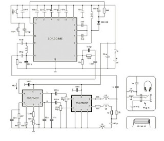
This UHF wideband signal amplifier has a total gain of 10 to 15 dB in the 400 - 850 MHz domain frequency so it can be used where the tv signal is weak. For UHF TV signal amplifier to work correctly, you need to cut the components pins as short as possible. C1, C2, C6, C7 are SMD type (surface mounted). This antenna tv amplifier or uhf wideband amplifier need to be build inside of a metal box and then connected close to the tv antenna.

The power supply is a simple 12V stabilized source. The tv antenna amplifier can be connected directly to the power supply thru coaxial cable of the tv antenna but you need a 10 - 100uH coil on the alimentation line. The tv set will be connected to the uhf amplifier thru a small coupling capacitor. Adjusting is easy, just bring the P1 to the middle and then adjust it untill you obtain the best tv image quality.

Components:

L1 = L2 = 2 turns, 3mm Ø

L3 = L4 = 10uH or 10 turns, 0.2mm Ø on ferrite

T = 2SC3358
Read More..

Tuesday, November 11, 2014

78L05 7805 based 5V regulator circuit with explanation

This is a very simple article, just trying to help ….
What is the most vital piece we always need in electronics? The answer is …. a good power supply, right? :D .
The best regulators for using in electronic projects are the 78LXX (78L05, 78L09, 78L12, 78L15 … ). I searched google for the application notes and I found them easily (look in the bottom part of the page for the download link).
Their typical application was the IC + 2 small condensers (the input is at 0.33uF and the output is at 0.01uF), but after some tryouts and more googling I found this page which, too be honest with you, I consider it to be the best circuit over the web.
I tested the circuit and it worked like charmed.
Reading the application note we see that the input voltage must be between 7V and 20V and the output voltage is between 4.75V – 5.25V
Components:
  • IC1 = 78L05 / 7805
  • D1 = 1N4007
  • C1 = 100uF
  • C2 = 10uF
Bibliography :
  • http://www.pmb.co.nz/psu_general_1.htm
  • http://www.national.com – The official manufacturer page
  • The 78L05 Datasheet : http://www.national.com/ds/LM/LM78L05.pdf
Read More..

Sunday, November 9, 2014

LCD Module in 4 bit Mode

In many projects use is made of alphanumeric LCDs that are driven internally by Hitachi’s industry-standard HD44780 controller. These displays can be driven either in 4-bit or 8-bit mode. In the first case only the high nibble (D4 to D7) of the display’s data bus is used. The four unused connections still deserve some closer attention. The data lines can be used as either inputs or outputs for the display. It is well known that an unloaded output is fine, but that a floating high-impedance input can cause problems. So what should you do with the four unused data lines when the display is used in 4-bit mode? This question arose when a circuit was submitted to us where D0-D3 where tied directly to GND (the same applies if it was to +5 V) to stop the problem of floating inputs.

The LCD module was driven directly by a microcontroller, which was on a development board for testing various programs and I/O functions. There was a switch present for turning off the enable of the display when it wasn’t being used, but this could be forgotten during some experiments. When the R/Wline of the display is permanently tied to GND (data only goes from the microcontroller to the display) then the remaining lines can safely be connected to the supply (+ve or GND). In this application however, the R/Wline was also controlled by the microcontroller. When the display is initialised correctly then nothing much should go wrong. The data sheet for the HD44780 is not very clear as to what happens with the low nibble during initialisation.

Circuit diagram :

LCD Module in 4-bit Mode Circuit Diagram

After the power-on reset the display will always be in 8-bit mode. A simple experiment (see the accompanying circuit) reveals that it is safer to use pull-down resistors to GND for the four low data lines. The data lines of the display are configured as outputs in this circuit (R/Wis high) and the ‘enable’ is toggled (which can still happen, even though it is not the intention to communicate with the display). Note that in practice the RS line will also be driven by an I/O pin, and in our circuit the R/W line as well. All data lines become high and it’s not certain if (and if so, for how long) the display can survive with four shorted data lines. The moral of the story is: in 4-bit mode you should always tie D0-D3 via resistors to ground or positive.
Read More..

Saturday, November 8, 2014

Portable Muscular Bio Stimulator

This is a small, portable set, designed for those aiming at look improvement. The Bio-Stimulator provides muscles stimulation and invigoration but, mainly, it could be an aid in removing cellulite. Tape the electrodes to the skin at both ends of the chosen muscle and rotate P1 knob slowly until a light itch sensation is perceived. Each session should last about 30 - 40 minutes.

Circuit diagram :

Portable Muscular Bio-Stimulator Circuit Diagram

C1 generates 150µSec. pulses at about 80Hz frequency. Q1 acts as a buffer and Q2 inverts the polarity of the pulses and drives the Transformer. The amplitude of the output pulses is set by P1 and approximately displayed by the brightness of LED D1. D2 protects Q2 against high voltage peaks generated by T1 inductance during switching.
Parts :
  • P1-----4K7 Linear Potentiometer
  • R1-----180K   1/4W Resistor
  • R2-----1K8  1/4W Resistor (see Notes)
  • R3-----2K2  1/4W Resistor
  • R4-----100R   1/4W Resistor
  • C1-----100nF  63V Polyester Capacitor
  • C2-----100µF  25V Electrolytic Capacitor
  • D1-----LED  Red 5mm.
  • D2-----1N4007  1000V 1A Diode
  • Q1,Q2-----BC327  45V 800mA PNP Transistors
  • IC1-----7555 or TS555CN CMos Timer IC
  • T1-----220V Primary, 12V Secondary 1.2VA Mains transformer (see Notes)
  • SW1-----SPST Switch (Ganged with P1)
  • B1-----3V Battery (two 1.5V AA or AAA cells in series etc.)
Notes :
  • T1 is a small mains transformer 220 to 12V @ 100 or 150mA. It must be reverse connected i.e. the 12V secondary winding across Q2 Collector and negative ground, and the 220V primary winding to output electrodes.
  • Output voltage is about 60V positive and 150V negative but output current is so small that there is no electric-shock danger.
  • In any case P1 should be operated by the "patient", starting with the knob fully counter-clockwise, then rotating it slowly clockwise until the LED starts to illuminate. Stop rotating the knob when a light itch sensation is perceived.
    Best knob position is usually near the center of its range.
  • In some cases a greater pulse duration can be more effective in cellulite treatment. Try changing R2 to 5K6 or 10K maximum: stronger pulses will be easily perceived and the LED will shine more brightly.
  • Electrodes can be obtained by small metal plates connected to the output of the circuit via usual electric wire and can be taped to the skin. In some cases, moistening them with little water has proven useful.
  • SW1 should be ganged to P1 to avoid abrupt voltage peaks on the "patients" body at switch-on, but a stand alone SPST switch will work quite well, provided you remember to set P1 knob fully counter-clockwise at switch-on.
  • Current drawing of this circuit is about 1mA @ 3V DC.
  • Some commercial sets have four, six or eight output electrodes. To obtain this you can retain the part of the circuit comprising IC1, R1, R2, C1, C2, SW1 and B1. Other parts in the diagram (i.e. P1, R3, R4, D1, D2, Q2 & T1) can be doubled, trebled or quadrupled. Added potentiometers and R3 series resistors must be wired in parallel and all connected across Emitter of Q1 and positive supply.
  • Commercial sets have frequently a built-in 30 minutes timer. For this purpose you can use the Timed Beeper the Bedside Lamp Timer or the Jogging Timer circuits available on this Website, adjusting the timing components to suit your needs.
Read More..

Cable TV amplifier With 2 Transistors

This is a actual simple cable TV amplifier application two transistors. This amplifier ambit is a lot of acceptable for cable TV systems application 75 Ohm coaxial cables and works accomplished up to 150MHz. Transistor T1 performs the job of amplification. Up to 20dB accretion can be accepted from the circuit.T2 is active as an emitter addict to access accepted gain.

Notes.
  • The circuit can be assembled on a Vero board.
  • Use 12V DC for powering the circuit.
  • Type no of the transistors are not very critical.
  • Any medium power NPN RF transistors can be used in place of T1 and T2.
  • This is just an elementary circuit. Do not compare it with high quality Cable TV amplifiers available in the market.
Read More..

Car Battery 12v Charger

The usual chargers of battery automotive, are simple and cheap appliances that charge continuously the battery, with a rythm of few amperes, for the time where the appliance is ON. If the holder do not close in time the charger, the battery will overcharge and her electrolytic faculty are lost with evaporation or likely exists destruction of her elements. The charger of circuit exceeds these faults. It checks electronic the situation of charge of battery and it has circuit of control with retroaction, that forces the battery charge with biggest rythm until charge completely.
Circuit diagram:

Car Battery 12v Charger Circuit Diaram
When charge completely, it turns on one RED led (LD2). The charger has been drawn in order to charge batteries of 12V, ONLY. What should watch it from what it manufactures the circuit, they are the cables that connect the transformer with the circuit and in the continuity the battery, should they are big cross-section, so that heat when it passes from in them the current of charge and also they do not cause fall of voltage at the way of current through them.
Adjustment
After assembling of the circuit, adjust TR1 to null value, power-up and make the following adjustments :-
  1. Without connecting the battery check that the 2 LED?s are turned on.
  2. Connect a car battery to the circuit and check that LD2 is OFF and a current (normally 2A to 4A) is flowing to the battery.
  3. Adjust TR1 until LD2 turns ON and the charge current is cut.
  4. Adjust TR1 to null value and charge the battery using the hydrometer technique (if you do not have or do not know how to use a hydrometer, then use a good condition battery and charge).

Carefully adjust TR1 so that LD2 begins to turn ON and the charge current falls to a few hundred milliamps (mA). If TR1 is set correctly then in the next round of charging you will noticed LD2 begin to flicker as the battery is being charged. When battery is completely charged, LD2 turns ON completely.TR1 does not need further adjustment anymore. Q1 is connected in line with the battery and is fired by R3, R4 and LD2. The R2, C1, TR1 and D2 sense the voltage of the battery terminal and activate Q2 when the voltage of the battery terminal exceeds the value predetermined by TR1.

When an uncharged battery is connected, the terminal voltage is low. Under this circumstance, Q2 is turned OFF and Q1 is fired in each half cycle by R3, R4 and LD2. The Q1 functions as a simple rectifier and charges the battery. If the battery terminal voltage is increased above the level that had been fixed by TR1, then Q2 shifts the control of Q1 gate. This deactivates Q1 and cuts off the current supply to the battery and turns LD2 ON indicating that the charge has been completed. Q1 and bridge rectifier GR1 should be mounted on heatsinks to prevent overheating. M1 is a 5A DC ammeter to measure the charge current
Read More..

Friday, November 7, 2014

BA5406 Stereo Amplifier Circuit

In the circuit diagram shown, BA5406 is configures to deliver 5×2 watts into 4 ohm loudspeakers at a supply offer voltage of 9 volts. Capacitor C3 is a power supply filter capacitor. C11 and C12 are input DC decoupling capacitors for the left and right channels. C3 and R2 forms a Zobel network for the left output whereas C6 & R3 forms identical for the correct channel.

Purpose of the Zobel network is to cut back oscillations and improve high frequency stability of the amplifier. Potentiometers R5 and R6 serves as the quantity control for the left and right channels. CapacitorsC4 and C8 couple the outputs of the amplifier to the speakers. C9 and C10 are noise filtering capacitors. C1 and C5 are bootstrap capacitors for the left and right channels.
Read More..

Morning Alarm Circuit Diagram Using LDR

Description Circuit showing a morning alarm.Here we have used a switching transistor.When the sun rise up ldr is low resistance so the ldr is conduct and a positive volt coming to the base of the Q1 there for the transistor will switch.This time  the buzzer is ON . Adjust the preset control the intensity of light.
Component Required                Resistor  4.7k preset  , LDR
Read More..

Thursday, November 6, 2014

Multi Color LED

How many different conditions do you reckon may be signalled with just one LED? Two, maybe three? Using this simple circuit, a lot more!

Admittedly, a two-colour LED is used here. Such a device consists of two light-emitting chips, usually red and green, encapsulated in the same case. It has three pins: two for the anodes, and one for the common cathode. In this way, each diode can be activated separately. Various mixed colours may be obtained by varying the current through the two diodes. At least four discrete colours are then easily perceived: pure red, pure green, orange (IR ≈ 2IG) and yellow (IG ≈ 2IR).

In the present circuit, the LED elements are driven by CMOS three-state buffers type 4503, which, unlike most CMOS ICs from the 4000 series, are capable of supplying up to 10 mA of output current. The LED cur-rents are limited by resistors R1 through R6, whose values invite experiments with brightness and colours according to your own taste.


Simple Multi-Color LED Circuit diagram:

Simple


The circuit was originally developed to indicate the state of three inputs, a, b, and c (non-binary, i. e., only one of these is at 1 at any time), with the con-figuration (a=b=c=0) representing the fourth state. The latter is decoded by NAND gate IC1. An additional effect is produced by gates IC1a and IC1b, which are connected up into an oscillator circuit producing approximately two pulses per second.
These pulses are used to control the common-enable input, DA (pin 1) of the 4503, so as to produce a flickering effect. The oscillator is controlled by means of inputs ‘d’ and ‘e’. Pulling both of these logic high disables the oscillator and the LED driver. With e=0 and d=1 the outputs of the 4503 are switched to three-state, and the circuit is in power-down standby mode.

Although designed for a 12-V supply voltage, the circuit will happily work at any supply volt-age between 5 V and 16 V. Non-used inputs of CMOS ICs must, of course, be tied to ground via 10-100 kW resistors.


Read More..

Wednesday, November 5, 2014

Cut rate Motorbike Alarm

Here is an alarm that’s loud, cheap and simple  to build. Arming and disarming the alarm is  done with a hidden switch, S1. This tiny circuit  does not unduly load the battery, as it draws  very little current in the standby condition. To activate the alarm, turn or press the hid-den switch S1 to the ‘on’ position. If anyone  attempts to start the motorbike, +12 volts  from the ignition switch (connected to ‘B’)  causes transistor T1 to conduct and switch on  T2. The siren (LS1) then sounds for about 20  seconds, the period being determined by FET  T3 wired as a monostable timer. The siren is  a high-power ready-made piezo horn of the  self-oscillating type.

Cut-rate Motorbike Alarm Circuit diagram :

Another piezoelectric component in the cir-cuit has a different purpose — Bz1 detects  attempts to tamper with the vehicle, or move  it without starting the engine. The piezo trans-ducer element should be mounted in such a  way as to faithfully pick up vibration from the  motorbike frame due to tampering.

One set of contacts on relay RE1 is used to  effectively disconnect the ignition coil to pre-vent the bike from functioning when some-one tries to steal it. Usually, there is a wire  running from the alternator (point A) to the  ignition coil (TR1), which has to be routed  through the N/C (normally closed) contact  of the relay. The hidden switch S1 is preferably a miniature type or its electrical equivalent. To deactivate the alarm, the hidden  switch should be flipped to the ‘off’ position  to disable the movement sensor and the siren driver/timer circuit when the ignition key is  turned… 
Read More..

3 Channel Audio Splitter

This circuit is suitable to amplify and distribute the audio signals. The input audio signal is applied to the J1 and after passing through the P1, It is buffered and amplified by the IC1 prepared to redistribute. It has 3 outputs to drive 3 audio lines with 300 ohms impedance.


3 Channel Audio Splitter Circuit Diagram :


Parts:

J1 = RCA Socket (See Notes)
P1 = 100K-Potentiometre
R* = 10K-100K
R1 = 560K
R2 = 1K
R3 = 2.2K
R4 = 2.7K
R5 = 2.7K
R6 = 330R
R7 = 330R
R8 = 330R
C1 = 100uF-25V
C2 = 100uF-25V
C3 = 100uF-25V
D1 = BZX79C18
D2 = BZX79C18
Q1 = BC337
Q2 = BC327
IC1 = NE5532-34

Notes:
  • J1 will be RCA Audio input female socket.
  • R* is on your choice it can be choose between 10K to 100K resistor.
  • Output capacitor’s value is between 100uf to 470uf and power handling is 25V to 50V.
  • You can power up this circuit via +12V/-12V regulated supply but you have to remove following parts Q1-Q2-C2-C3-D1-D2.
  • Maximum power ratings +35V/-35V
Read More..

MD Catridge Preamplifier

Phonographs are gradually becoming a rarity. Most of them have had to yield to more advanced systems, such as CD players and recorders or (portable) MiniDisc player/recorders. This trend is recognized by manufacturers of audio installations, which means that the traditional phono input is missing on increasingly more systems. Hi-fi enthusiasts who want make digital versions of their existing collections of phonograph records on a CD or MD, discover that it is no longer possible to connect a phonograph to the system.

 MD Catridge Preamplifier Circuit diagram:

Preamplifier

However, with a limited amount of circuitry, it is possible to adapt the line input of a modern amplifier or recorder so that it can handle the low-level signals generated by the magnetodynamic cartridge of a phonograph. Of course, the circuit has to provide the well-known RIAA correction that must be used with these cartridges. The preamplifier shown here performs the job using only one opamp, four resistors and four capacitors. For a stereo version, you will naturally need two of everything. Any stabilized power supply that can deliver ±15V can be used as a power source.


Read More..

Automatic Switch For Audio Power Amplifier

Automatic Switch For Audio Power Amplifier. Circuit of an automatic switch for audio power amplifier stage is presented here. The circuit uses stereo preamplifier output to detect the presence of audio to switch the audio power amplifier on only when audio is present.

The circuit thus helps curtail power wastage. IC1 is used as an inverting adder. The input signals from left and right channels are combined to form a common signal for IC2, which is used as an open loop comparator. IC3 (NE556) is a dual timer. Its second section, i.e., IC3(b), is configured as monostable multivibrator. Output of IC3(b) is used to switch the power amplifier on or off through a Darlington pair formed by transistors T1 and T2. IC3(a) is used to trigger the monostable multivibrator whenever an input signal is sensed.

Switch For Audio Power Amplifier Circuit Diagram:

Amplifier-Circuit-Diagram

Under ‘no signal’ condition, pin 3 of IC2 is negative with respect to its pin 2. Hence the output of IC2 is low and as a result output of IC3(a) is high. Since there is no trigger at pin 8 of IC3(b), the output of IC3(b) will be low and the amplifier will be off. When an input singal is applied to IC1, IC2 converts the inverted sum of the input signals into a rectangular waveform by comparing it with a constant voltage which can be controlled by varying potentiometer VR1. When the output of IC2 is high, output pin 5 of IC3 goes low, thus triggering the monostable multivibrator. As soon as the audio input to IC1 stops, pin 5 of IC3 goes high and pin 1 of IC3 discharges through capacitor C3, thus resetting the monostable multivibrator.

Hence, as long as input signals are applied, the amplifier remains ‘on.’ When the input signals are removed, i.e., when signal level is zero, the amplifier switches off after the mono flip-flop delay period determined by the values of resistor R8 and capacitor C3. If no input signals are sensed within this time, the amplifier turns off—else it remains on. Power supply for the circuit can be obtained from the power supply of the amplifier. Hence, the circuit can be permanently fitted in the amplifier box itself. The main switch of the amplifier should be always kept on. Resistors R1 and R2 are used to divide single voltage supply into two equal parts.

Capacitors C1 and C2 are used as regulators and also as an AC bypass for input signals. Diode D1 is used so that loading fluctuations in power amplifier do not affect circuit regulation. Transisitor T2 acts as a high voltage switch which may be replaced by any other high voltage switching transistor satisfying amplifier current requirements. Value of resistor R10 should be modified for large current requirement. The LED glows when the amplifier is on. The circuit is very useful and relieves one from putting the amplifier on and off every time one plays a cassette or radio etc. 


Read More..