Wednesday, August 13, 2014
Browse |
home»
a
»
build
»
circuit
»
converter
»
dc
»
diagram
»
isolated
|
Build a Isolated Dc Dc Converter Wiring diagram Schematic

Build a Isolated Dc Dc Converter Wiring diagram Schematic
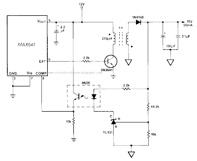
This Isolated Dc-Dc Converter Circuit Diagram, a TU31 shunt regulator is used to sense the output voltage. The TU31 drives the LED of a 4N28 optocoupler which provides feedback to the MAX641 while maintaining isolation between the input, +12 V, andJhe output, +15 V. ln this Isolated Dc-Dc Converter Circuit Diagram, the +15 V output is fully regulated with respect to both line and load changes.
Isolated Dc-Dc Converter Circuit Diagram

Subscribe to:
Post Comments (Atom)
No comments:
Post a Comment