Showing posts with label temperature. Show all posts
Showing posts with label temperature. Show all posts
Wednesday, November 12, 2014
Maximum Temperature Detector For Fan Controller
The fan controller circuit for the Titan 2000 and other AF heavy-duty power amplifiers, has an output that sets a voltage if the fan controller reaches the end of its range. Since the controller responds to temperature, this signal is seen by the amplifier protection circuitry as an over temperature indication. The disadvantage of this output is that the maximum voltage for the fans is not constant, but depends on the load (number of fans, defective fans) and the mains voltage. This variation is caused by the fact that the supply voltage for the output stage is taken directly from the filtered transformer voltage.![Maximum]() If the fans should fail, for example, the maximum temperature limit would lie at a considerably higher level than the desired value. The accompanying circuit, which compares the magnitude of the fan voltage to a fixed reference value, has been developed to allow the maximum temperature to be reliably detected. This circuit is tailored for 12-V fans. The reference voltage is generated by the ‘micro power voltage reference’ D1 and the FET T1, which is wired as a current source. These components are powered directly from the applied fan voltage. The current source is set up to deliver approximately 50µA.
If the fans should fail, for example, the maximum temperature limit would lie at a considerably higher level than the desired value. The accompanying circuit, which compares the magnitude of the fan voltage to a fixed reference value, has been developed to allow the maximum temperature to be reliably detected. This circuit is tailored for 12-V fans. The reference voltage is generated by the ‘micro power voltage reference’ D1 and the FET T1, which is wired as a current source. These components are powered directly from the applied fan voltage. The current source is set up to deliver approximately 50µA. D1 can work with as little as 10µA. The supply voltage for the IC is decoupled by R10, C3 and C4, with D4 providing over voltage protection. A maximum supply voltage of 16 V is specified for the TLC271. This opamp works with a supply voltage as low as 3 V and can handle a common-mode voltage up to approximately 1.5 V less than the positive supply voltage. Accordingly, 1.2 V has been chosen for the reference voltage. The fan voltage is reduced to the level of the reference voltage by the voltage divider R2–R3–P1. The limits now lie at 11.2 V and 16.7V.
 If you find these values too high, you can reduce R2 to 100 kΩ, which will shift the limits to 9.5 V and 14.2 V. The output of the voltage divider is well decoupled by C2. A relatively large time constant was selected here to prevent the circuit from reacting too quickly, and to hold the output active for a bit longer after the comparator switches states. A small amount of hysteresis (around 1 mV) is added by R4 and R5, to prevent instability when the comparator switches. D2 ensures that the magnitude of the hysteresis is independent of the supply voltage. Two outputs have been provided to make the circuit more versatile.
 Output ‘R’ is intended to directly drive the LED of an optocoupler. In addition, transistor T2 is switched on by the output of the opamp via R7 and R8, so that a relay can be actuated or a protection circuit triggered using the ‘T’ output. The high-efficiency LED D3 indicates that IC1 has switched. It can be used as a new ‘maximum’ temperature’ indicator when this circuit is added to the fan controller. The circuit draws only 0.25 mA when the LED is out, and the measured no-load current consumption (with a 12.5V supply voltage) is 2.7 mA when the LED is on.Resistors:
Read More..
 D1 can work with as little as 10µA. The supply voltage for the IC is decoupled by R10, C3 and C4, with D4 providing over voltage protection. A maximum supply voltage of 16 V is specified for the TLC271. This opamp works with a supply voltage as low as 3 V and can handle a common-mode voltage up to approximately 1.5 V less than the positive supply voltage. Accordingly, 1.2 V has been chosen for the reference voltage. The fan voltage is reduced to the level of the reference voltage by the voltage divider R2–R3–P1. The limits now lie at 11.2 V and 16.7V.
 If you find these values too high, you can reduce R2 to 100 kΩ, which will shift the limits to 9.5 V and 14.2 V. The output of the voltage divider is well decoupled by C2. A relatively large time constant was selected here to prevent the circuit from reacting too quickly, and to hold the output active for a bit longer after the comparator switches states. A small amount of hysteresis (around 1 mV) is added by R4 and R5, to prevent instability when the comparator switches. D2 ensures that the magnitude of the hysteresis is independent of the supply voltage. Two outputs have been provided to make the circuit more versatile.
 Output ‘R’ is intended to directly drive the LED of an optocoupler. In addition, transistor T2 is switched on by the output of the opamp via R7 and R8, so that a relay can be actuated or a protection circuit triggered using the ‘T’ output. The high-efficiency LED D3 indicates that IC1 has switched. It can be used as a new ‘maximum’ temperature’ indicator when this circuit is added to the fan controller. The circuit draws only 0.25 mA when the LED is out, and the measured no-load current consumption (with a 12.5V supply voltage) is 2.7 mA when the LED is on.Resistors:
- R1 = 22kΩ
- R2 = 120kΩ
- R3 = 10kΩ
- R4,R6 = 1kΩ
- R5 = 1MΩ
- R7,R8 = 47kΩ
- R9 = 3kΩ9
- R10 = 100Ω
- P1 = 5kΩ preset
- C1,C3 = 100nF
- C2 = 100µF 25V radial
- C4 = 47µF 25V radial
- D1 = LM385-1.2
- D2 = BAT85
- D3 = high-efficiency-LED
- D4 = zener diode 16V/1W3
- T1 = BF245A
- T2 = BC547B
- IC1 = TLC271CP
- K1 = 2-way PCB terminal block, raster 5mm
- K2 = 3- way PCB terminal block, raster 5mm

Saturday, October 4, 2014
12V Fan Temperature Controller
this simple design allows|permits an correct speed control of 12V dc fan motors, proportional to temperature. A n.t.c. Thermistor (R1) is employed as temperature sensor, driving two directly coupled complementary transistors wired during a dc feedback circuit. An optional circuitry was added to remotely monitor fan operation and to permit some type of rough speed indication by means that of the increasing brightness of a LED.
Notes:
- R5 must be set to allow motor just starting at the desired temperature.
- Any n.t.c. Thermistor in the 6K8 - 22K range value might work, provided R2 value is one/tenth of Thermistors value.
- R6, R7 and D1 are optional: R7 must be adjusted until the LED glows faintly when the motor is just running.
Tuesday, August 26, 2014
Simple Adjustable Threshold Temperature Alarm Wiring diagram Schematic
Simple Adjustable Threshold Temperature Alarm Circuit Diagram. This is a simple temperature alarm schema diagram, when Rl increases as temp decreases, the output of IC1 goes positive, turning on Ql. Ql conducts and causes Q2 to conduct, turning on the audible alarm. The threshold is set with potentiometer R2.
Adjustable Threshold Temperature Alarm Circuit Diagram
Friday, August 22, 2014
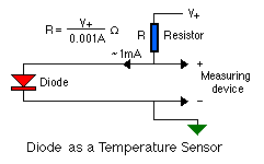
Simple Temperature Sensor Circuit using 1N4148 diode
There are components that have special characteristics, one of them is the 1N4148 diode, it is a diode High-speed, and its switching speed is 4th, its voltage is 100 V and current of 450 mA. It besides a diode 1N4148 is used as the temperature sensor, that due to its characteristics that cause it to change its resistance with temperature change. Of course it does not compare to a sensor like the LM38, but for some diagram of low precision, which just need to know if an element is hot or cold it is very useful.
Temperature Sensor Circuit using 1N4148 diode Diagram
Using the multimeter and the 1N4148 as a thermometer
The scheme above is a schema that measures the temperature in a simple manner using a multimeter. It uses 1N4148 diode, and VR1 and VR2 must be adjusted with a thermometer, and is more precise measurement. On the scale of the multimeter can be compared to the scale of degree Celsius with Volt.
The scheme above is a schema that measures the temperature in a simple manner using a multimeter. It uses 1N4148 diode, and VR1 and VR2 must be adjusted with a thermometer, and is more precise measurement. On the scale of the multimeter can be compared to the scale of degree Celsius with Volt.
Temperature sensor with diode 1N4148
If you liked this article,Take a few Seconds to Share this and leave comments
Subscribe to:
Posts (Atom)
