Friday, September 26, 2014
Simplest 220V LED Light Circuit
Isolation need to be supplied and the lights (LEDs) needs to be off from prying hands.
You will need a minimum of 50 LEDs in every single thread to stop them being harmed through a power upswing through the 1k resistor - in case the circuit is started up at the highest of the waveform. When you increase LEDs to each line, the current will reduce a very small quantity right up till, when you have 90 LEDs in each thread, the current will be nil.
For 50 LEDs in each thread, the whole feature voltage will be 180v to ensure that the peak voltage will be 330v - 180v = 150v. Each LED will find a lot less than 7mA highest while in the half-cycle they may be switched on. The 1k resistor may possibly cancel 7v - due to the fact the RMS current is 7mA (7mA x 1,000 ohms = 7v). Simply no rectifier diodes are needed. The LEDs are the "rectifiers." Really clever. You should have LEDs in both directions to charge and discharge the capacitor. The resistor is furnished to obtain a heavy surge current from one of the series of LEDs if the circuit is triggered whenever the mains is at a optimum.
This is often up to 330mA in the event only 1 LED is employed, therefore the benefit of this resistor needs to be modified as long as a couple of LEDs run. The LEDs above pick up apex current.
A 100n cap generates 7mA RMS or 10mA apex in full wave or 3.5mA RMS (10mA peak for one half a cycle) in half-wave. (when solely 1 LED remains in each sequence).

Alcohol Tester Circuit for Vehicle Drivers
Fit the gas sensor in the foremost part of the tube: if the diameter of the tube is slightly too large, wind some tin or aluminium foil around the sensor until the whole fits tightly. Under no circumstances should you use any glue near the sensor as this could give rise to spurious indications for a long time to come. The sensor should therefore be secured with a suitable aluminium or plastic hood as shown in the figure. The openings behind the sensor in the tube ensure that the sensor is well immersed in exhaust gas so that it works fairly rapidly. Furthermore, these openings prevent a build-up of gas behind the sensor (which is pervious to gases) that could give rise to spurious readings. The LEDs should be mounted in their sockets in the top moulding of the case. Spray a liberal quantity of lacquer over their terminals, or, better still, brush some two- component epoxy resin over them, which will make the whole sturdier in use.
Calibration: Operate the tester in the open air and, using P1, set the voltage on pin 8 of IC2 to a level between 1 and 3 V. If that is not possible, reduce the value of P1. Next let the gas sensor heat up for at least a couple of hours. The setting of the thresholds of the window discriminator to correspond to 1 per cent and 4.5 per cent CO content requires the use of a reference tester. Many garages, MOT testing stations, as well as the test centres of the AA and RAC have such a unit, and you should be able (during a quiet period) to get the use of it for a little while. During the measurement hold the preheated gas sensor in the gas stream about 10 cm from the exhaust outlet. After a short while, the sensor has stabilized and can then be compared with the reference. Adjust the choke (engine running!) so that the reference meter indicates a CO content of 4.5 per cent.
On the CO tester set P2 such that the red LED just does not light: if you really love the environment, set P2 so that the red LED just lights. Follow the same procedure with a CO content of 1 per cent (hopefully this is possible), but in this case adjust P3 until the yellow LED just lights. As already stated before, the accuracy of measurement is set between narrow limits; none the less, the CO tester makes it possible to check the cleanliness of your engine regularly and conveniently. It is possible to power the tester from the cigarette lighter via a suitable two-core cable (about 3 m long): a plug for this purpose is obtainable from most good car accessory shops.
the proposed alcohol gas sensor proper is based on a mixture of chemical and physical properties. Basically, when heated, it behaves like a resistance of which the value diminishes when the CO content increases. Perhaps that is putting it a little too simple, because the sensor reacts not only to carbon monoxide, but also to a number of other gases and gaseous substances in the atmosphere, from alcohol, which is blue but indicated by the red LED, through propane and butane to the carbon hydroxides (found, for instance, in stink bombs). This is illustrated in figure below. None the less, the primary harmful constituent of the exhaust gases is carbon monoxide which is detected with great accuracy. Flashing of the LEDs indicates that the tester is not yet ready for use, because the gas sensor has not heated up. Only when the LEDs stop flashing, that is, after about 3. . .5 minutes, can the measurements be commenced.
Construction hints for the alcohol tester circuit
First, the voltage regulator, IC1. This integrated device provides a stabilized supply of 5 V at a maximum current of 1 A from the pulsating battery voltage. Capacitors C1 and C2 provide further smoothing of the supply voltage. The heating element of the gas sensor is connected in parallel with the regulator. Both IC1 and the sensor get noticeably warm during use and IC1 is therefore fitted onto a heat sink which improves heat conduction in the closed case. The regulator also provides thresholds for comparator lC2 which are preset by P2 and P3.


Thursday, September 25, 2014
Central Heat Controller Circuit
It measures the water temperature, and arranges for a particular valve or pump in the system to be switched on to achieve a user-defined temperature distribution in the home. Residual heat in the central heating system can thus be used to lower the cost of fuel. Fig. 1 shows that water in temperature range I can be used for the central heating and the storage vessel, while that in range II is also suitable for directing to the boiler. In most cases, it is not recommended to re-use water with a temperature below 30 °C. The circuit arranges for an alarm to be activated when the water temperature falls below 5°C, or exceeds 95 °C. The circuit diagram of the central heating control appears in Fig. 2. Relays Re1 and Res are activated upon measuring the maximum and minimum permissible temperature, respect- ively.
The temperature sensor is a Type LM35, which has a scale factor of +10 mV/°C. Its output voltage is amplified in At and fed to the non-inverting inputs of comparators A2-A6. The presets at the inverting input of each of these is used to set the toggle voltage, i.e., the temperature at which the relevant relay is switched on or off. The relay drivers are open-collector power buffers with built-in freewheeling diodes to afford protection against inductive surges.
The use of the Type ULN2003 makes it possible to use relays with a coil voltage of upto 50 V without the need for additional interfacing. Each temperature setting has a hysteresis of about 2 °C. Transistors T1-Ta serve to disable the previously energized pump or valve upon detecting a water temperature that falls within another, predefined, range. In this manner, only one relay is activated at a time. It stand to reason that the temperature sensor, IC1, must be mounted such that it is in thermal contact with the water in the heating system. Make sure that the device is well-insulated, and that it does not cause leakage. The temperature range settings for the presets are shown opposite.

FM Radio Receiver Antenna Booster Circuit
 This affordable FM radio receiver antenna enhancer makes use of the BF324 TO92 type pnp transistor in a grounded-base arrangement.
The circuit can be utilized like a signal booster with VHF receivers whose front end is afflicted with reduced level of sensitivity (like a lot of valved and army supplemental variations). The frequency selection of the preamplifier is approximately from 75MHz to 150MHz.
The 2 inductors in the circuit are do-it-yourself. L1 includes 10 turns of 24SWG enameled copper wire; the inner dimension is 3mm, without any core. Inductor L2 bears 13 flips of the identical wire, as well as an inner diameter of 5mm; without core as above. A building tip: tight-wind the inductors making use of three and 5mm drill bits respectively in the form of momentary cores.
The prototype of the preamplifier was effectively tried with an 88-108 MHz FM broadcast receiver along with a 2-metre VHF ham receiver. The preamplifier consumes around 2.5mA from a 5-volt supply.
Sine Wave Oscillator Circuit
lf the overall gain, including feedback, exceeds unity the circuit will produce sine wave oscillation at a frequency set by the Wien network. Stabilisation of the gain is brought about by the action of diodes D1 and Dl% then the instantaneous output voltage is close to zero, neither diode conducts, since even a germanium diode requires 0.4 volts or so forward voltage to bias it on. Consequently, the negative feedback loop is open (giving maximum gain) and, under the action of the positive feedback via the Wien network, oscillations build up rapidly. As soon as their amplitude is sufficient to bias on either Dl or D2 (depending on the polarity of the output voltage swing), then R2, R3 and RV2 provide negative feedback, so limiting oscillations to a convenient level. Reinforcement of such oscillations takes place close to each zero crossing when D1 and D2 are open ire. non·conducting; the setting of RV2 determines the final amplitude.
This method of stabilisation does give rise to a very small amount of crossover distortion, but the effect of this can be minimised by setting VR2 for the largest possible sine wave without clipping. ln any event, some distortion is a small price to pay for such a simple, easy-to~get—working sine wave oscillator and, further, it is a low level of distortion — some class B audio amplifiers are worse! Range switching is confined to a choice of two ranges, in the interest of simplicity and cheapness, but more ranges could easily be provided if the constructor is so inclined. A simple emittentouower output stage completes the unit, with a logarithmic potentiometer as a level control, enabling the output to be set from 1 V rms down to 10 mV rms or so. With wiring up completed and thoroughly checked, switch on and, if possible, monitor the output on an oscilloscope. No ’scope? Then a pair of headphones, of reasonably high impedance, can be used instead. Set RV4 about half way, S1 to "low" and RVI about half way. lf there is no output, adjust RV2; clockwise rotation should give increased output. With an ac meter, measure the signal level at the junction of D1, D2 and RV2. Adjust RV2 for 3 volts rms. This will ensure the highest output level (thus reducing the effect of crossover distortion) consistent with sine wave operation (no`clipping). This should provide about one volt rms at the output.

Wednesday, September 24, 2014
Simple Schmitt Trigger Circuits

One cheap IC, ul.914, can be used as an extremely simple and effective Schmitt trigger suitable for many applications. Hysterisis of the circuit is about 0.1 Volt. This may be varied by altering the values of R1 and R2.

An LED and phototransistor optical coupler system may be used to lengthen a three microsecond pulse to 55 milliseconds by using the values shown in the diagram. This allows complete isolation between input pulse circuits and the lengthener to be obtained.

Simple Baud Rate Generator Circuit IC 4060 Output Pin Out Configurations

Each serial data interface requires a baud rate generator: terminal, printer tape interface. . . lt is often not possible to use the same generator for input and output, so it would be useful to add one to, for instance, the UART in the computer or the UART in the terminal. To keep the ,costs of such an addition down, we have developed a generator which uses just one IC, two resistors, one preset potentiometer and a capacitor. The CMOS 4060 is a 14-stage binary counter with an internal oscillator which only requires the frequency determining RC components. As the reset is connected to earth, the counter begins to count upwards when the supply is switched on. A clock frequency then becomes available at the outputs: the higher the number of the output, the lower the frequency available at it.
In the circuit shown the frequencies avail- able at the various outputs are: O4 = 9600 baud 08 = 600 baud 05 = 4800 baud O9 = 300 baud O6 = 2400 baud Q10 = 150 baud Q7 = 1200 baud If the outputs are wired as shown in the circuit diagram, the required baud rate can then be selected by means of a wire link. _ The oscillator frequency can be set precisely with P1, and measured either at pin 9 of the 4060 or at one of the outputs O4 . . . Q10. With the values shown, the frequency at pin 9 should be 38.4 kl-lz; at the outputs O4. . .010 the relevant baud rate. lt is often required that the clock frequency is 16 times the baud rate (for instance, with asynchronous ~ operation of the 6850, 8251, 280- SIO. . .). ln that case, C1 must be replaced by a 27 nF capacitor and the oscillator frequency must be set to 614.4 kHz.
10 km Long Range Transmitter Circuit 2 meter band

The theoretical circuit is given in Fig. 1 and consists of a Colpitt’s oscillator using 8MHz crystals. Six channels are shown in the schematics—three, in fact, `T were used for the prototype but there is no reason why many crystals cannot be included by using a suitable multiway switch and increasing the number of islands on the board; using the smaller HC25 series crystals would permit more channels to be fitted in the space allotted. The trimmers in series with each crystal allow easy netting to the assigned frequency. The f.m. is applied to the oscillator by a reactance stage, fed by two audio pre-amps. Deviation is con- trolled by a 10kQ potentiometer and the maximum attained on the prototype was 8kHz. Notice the inclusion of decoupling in the audio stages to prevent r.f. pickup so often a cause of poor audio quality in home·constructed equipment. The printed board layout is shown in Fig. 2.
Making PCBs
Cut a piece of single-sided copper board to the size shown and with some {ine abrasive paper, clean the copper surface to remove any oxide or tarnish.
Using a soft, lead pencil, draw out the islands on the board, and then draw around these and the inter- connections of the earth plane edge. The small islands and fine connections are then filled in by means of an etch-resist pen or ine paint brush, using quick drying paint, such as car touch-up paint, thinned down if necessary. The larger areas are then put in care- fully and when the board is dry, each island and connection examined to make sure no copper bridges exist between them. One should also ensure adequate clearances.
Place the board in a suitable plastic or earthen- ware container and pour on just sufficient ferric chloride solution as is necessary to cover it. The solution can be purchased ready-mixed from most radio component stores, or can be made up by a chemist. It is however a corrosive, albeit a mild one, so handle carefully and wash off any of the solution that comes into contact with the skin immediately.
Initially, leave the board submerged for about twenty minutes, agitating occasionally. You will see the chemical action taking place quite clearly and when all the unwanted copper has been eroded, take out the p.c.b., wash in clean water and then dry. Using a wet abrasive pad such as a Brillo pad- the paint is now removed and a final wash and dry will leave the copper gleaming. After a final check of the work, drill the mounting holes for fixing to the metal chassis.
Each board in the transmitter is etched in this way and provided the simple instructions are followed you should easily be able to provide good examples.
Mounting Components
There is no hard-and-fast rule about fixing the components to the board, but the Author favours soldering the resistors first, followed by the capacitors, the coils and finally the transistors. Keep lead lengths short typically 6-12mm for transistors and solder neatly, holding the iron in place just long enough for the solder to flow to the joint. An iron of 15W rating with a bit size of 3mm or so is to be preferred for work of this nature.
Testing the long range transmitter circuit
Connect a 15 volt supply to the board having first established that the polarity is correct and check the voltages shown: a 15 per cent error is quite acceptable, due to component tolerances. With a 6009 microphone and a pair of earphones across C11 to the earth line, check for clean audio and the operation of the deviation control. The oscillator can be tested by connecting a suitable 8MHz crystal in position (i.e. 8-08335MHz for S20-145-5MHz) and listening for the 8MHz signal on a tunable h.f. receiver, coupled loosely to the vicinity of the oscillator stage.
After this feed an audio signal at the input and try to receive this over any standard 2 mtere band receiver unit placed at about 10 meters distance.
With little trial and error you would be able to receive a crystal reception, done! Now you can take the unit to some other far away location and confirm the same.


Power Inverter 1000 Watt by Mosfet

This power inverter circuit will provide a very stable “Square Wave” Output Voltage. Frequency of operation is determined by a pot and is normally set to 60 Hz. Various “off the shelf” transformers can be used. Or Custom wind your own for best results.

The Power leads must be heavy enough wire to handle this High Current Draw! appropriate Heat Sinks Should be used on the RFP50N06 Fets. These Fets are rated at 50 Amps and 60 Volts. Other types ofMosfets can be substituted if you wish.

Note
There ARE Limitations! I have had numerous requests for an Inverter for 1000 watts and Even MORE. Sorry I Don’t feel this is Practical. At 1000 Watts and operating from a 12 Volt Source, the Input Current will be close to 100 AMPS. That would Require a HUGH Size of a Primary Wire.
Monday, September 22, 2014
NJM2035 Stereo Encoder Multiplexer Kit

This package comes with components and instructions that are needed to build simple but high quality stereo encoder. The circuit connects to any mono FM transmitter and converts it into HI-FI stereo transmitter. The project can be supplied with as little as 1.2 Volts, up to 3.6 Volts. The circuit also has built-in stereo pre-emphasis to enhance and produce a crystal clear sound. NJM2035 is manufactured by NJR CORPORATION (JRC), a subsidiary of New Japan Radio, a company that is known as the worlds best manufacturer of high end professional audio semiconductors.
Component List
1x NJM2035
1x Stereo Encoder PCB
1x 38KHz Crystal
1x 33uF Capacitor
1x 10uF Capacitor
3x 100nF Capacitor
2x 1nF Capacitor
1x 100pF Capacitor
1x 10pF Capacitor
1x 82K Resistor
2x 47K Resistor
2x 27K Resistor
1x 10K Resistor
1x Schematic with Instructions
275W Leach Amplifier
Privacy speakers are powered directly from the voltage amplifier. As for mechanical design, is probably the most complicated in the whole amplifier. Cooling is done by the Al blocks that are attached to the main cooling profile. ZH6465 profile is used. The terminal transistors to heat is released through Al strips with a thickness of 6 mm in the lateral beams and passing into the cooler. more pictures.
Output power: 275W RMS (when supply +-66v)
Minimum holiday zázěž: 4R
Slew rate: 35V/us
Bandwidth: 8-150 000 Hz /-3dB
Maximum permissible voltage: +-65V
Filter Capacity: 2 x 15G / 80V
Sensitivity DC protection: + /-2V
Late connection: 2 seconds
Fusing end amplifier: 2x 6.3 A / F
Input sensitivity for maximum excitation: 1.55 V


Sunday, September 21, 2014
Mercedes Explanation Fuse Box Year Benz 2001 CLK 320 Diagram
Fuse Box Mercedes Benz 2001 CLK 320 Diagram
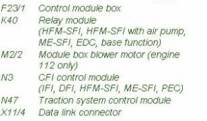

Fuse Panel Layout Diagram Parts: control module box, relay module, air pump, blower motor, CFI control module, traction system control module, data link connector.
Fuse Box Ford 2001 Escape Under Hood Diagram
Fuse Box Ford 2001 Escape Under Hood Diagram


Fuse Panel Layout Diagram Parts: horn, headlamp, high beam relay, EEC.
Mercedes Explanation Fuse Box Year 1989 230 Fuel Injection Diagram
Fuse Box Mercedes 1989 230 Fuel Injection Diagram


Fuse Panel Layout Diagram Parts: gear start relay, combination relay, power seat relay, auxiliary fan, preresistor relay, headlamp washer relay, auxiliary fuse holder, power seat diode, parking brake, electronic accelerator, exterior lamp failure monitoring unit, air injection relay, power window relay, convenience relay, seat belt warning relay.
Saturday, September 20, 2014
Fuse Box BMW R1150GS 2000 Diagram
Fuse Box BMW R1150GS 2000 Diagram


Fuse Panel Layout Diagram Parts: Side light, Driver information display, ABS warning relay, Flasher unit, Dial needle damping, Socket, Horn, Motronic, Coding plug Motronic, Horn relay, Fuel pump relay, Motronic relay, Brake light, Tail light, Starter relay, Load relief relay, Diagnostic connector, Fuel pump, Heated handles, Istrument cluster, Dial needle damping,
Fuse Box Acura 1999 CL Diagram
Fuse Box Acura 1999 CL Diagram


Fuse Panel Layout Diagram Parts: daytime running light, starter signal, heater control, AC clutch, ignition coil, spare fuse, wiper/washer, master light, clock security, spare fuse, ECU, cruise control, fan timer, SRS, fuel pump, back up light, turn signal, cooling fan relay, power mirror, mirror heater, spare fuse, ABS motor, ABS unit, Radio.
Friday, September 19, 2014
Simple 4 Channel Video Amplifier using NJM2582
A very simple 4 channel video amplifier electronic circuit project can be designed using NJM2582 ic suitable for video applications with SCART connector . Design of the circuit is very simple and require few external electronic parts .
Circuit diagram :

Simple 4 Channel Video Amplifier Circuit Diagram
Some features of the NJM2582 are : Operating Voltage ±5V, +5V, +11V ; 6input 4output , 2input 1output Video SW , Internal LPF , 6dB Amplifier , Internal 75Ω Driver Circuit , DC output for SCART (FUNCTION SW, BLANKING) .
Fuse Box BMW Z4 Coupe 2007 Diagram
Fuse Box BMW Z4 Coupe 2007 Diagram


Fuse Panel Layout Diagram Parts: turn indicator, hazard warning flasher, comp. light, low beam headlight, airbag, high beam headlight, brake light, side light, ASC/DSC, CD charger, central locking system, cigar lighter, clutch switch, interior and luggage,
Fuse Box Toyota Camry Diagram
Fuse Box Toyota Camry Diagram


Fuse Panel Layout Diagram Parts: daytime running light, high current, Head relay, EFI relay, engine main relay, COS fuse, main fuse,
Luxurious Toilet Bathroom Facility

The operational features of the circuit are:
- Lamp and exhaust fan are switched on when the door is opened.
- Soft music is played continuously until the door is closed from inside/out side.
- With a person inside the room, lamp and fan remain on, until the door is reopened. They go off when the door is reopened.
- Visual indication of whether the toilet/bathroom is occupied/vacant is given by two bicolour LEDs fixed on a panel, which may be fitted near the door with corresponding ‘toilet’/’bathroom’ labels on them. Here the LED colour turns from ‘green’ to ‘red’ if the room gets occupied, and vice-versa.
- If the door is opened once, and not closed back within 10 seconds, the lamp and fan are automatically switched off, thus conserving electricity. But the music remains on as a reminder that the door is not closed.
- For cleaning of bathroom/toilet with doors kept open, a parallel on/off switch is included on the switchboard to bypass the relay contacts and manually control the switching on/off of the light and exhaust fan. (This is the service mode.) In this case, the music remains on as long as the door remains open. In case of failure of the unit, the same on/off switch can be used as usual until the circuit is repaired.
- Due to battery backup facility, even with power failure, when a person is inside, the door status is maintained. However, the lamp and fan will be on only on mains resumption.
- Also, when a person leaves the room during power failure, with door closed, the lamp and fan are kept off on resumption of power. (Intelligent-mode!)
- However, the circuit can be fooled by opening and closing the door within 10 seconds, without entering inside. In this case, the lamp and fan will continue to be on and would require reopening and closing of the door to bring the circuit to order.

Simultaneously, pin 2 (Q) of IC1(a) goes low, switching transistor T5 ‘on’, which switches on melody generator IC4, letting out a sweet audio tune via transistor T6 and loudspeaker. In normal condition, when someone opens the bathroom door and gets inside within preset time of IC3(a) (10 seconds here), and closes the door from inside, the music stops with lamp and fan ‘on’. Now, in case someone opens the door before or after use, and forgets to shut it, the lamp and exhaust fan are switched off after 10 seconds but the music remains ‘on’ as a reminder that the door is to be closed.
This happens due to mono multivibrator (MMV) IC3(a), which resets pin 10 of IC1(b) through transistor T1 after 10 seconds. (This period can be adjusted by varying the values of resistor R11 and/or capacitor C7.) It should be noted here that although IC3 is used as ‘MMV’, it is triggered here with a positive pulse through its pin 4 (reset pin) rather than its pin 6 (trigger pin). This arrangement makes it unique for setting and resetting IC3 through pin 4, and resetting IC1(a) through pin 5 of IC3 and transistor T1. Battery backup facility ensures memory backup during power failure. Power supply uses a normal 2-diode full-wave rectifier circuit, which needs no further explanation.
The purpose of using bi-color LED1 and LED2 is that, initially when the door is closed these emit green light— as the green LED part gets the supply via resistor R15— to indicate that bathroom/toilet is vacant. When bathroom/toilet is occupied, transistor T3/T4 conduct to light up the red LED part as well. Melody generator IC4 (UM66) is switched on through diodes D3/D4 and transistor T5, which conducts when IC1(a) pin 2 or IC2(a) pin 2 goes low. When transistor T5 conducts, zener ZD1 breaks down and supplies regulated 3.9V to IC4, to produce a melodious tune via transistor T6 and the speaker. As most toilets and bathrooms are ‘attached’ nowadays, only a single circuit is required, and the circuit can be wired on a general-purpose veroboard. A small modification of the circuit, by adding additional SPST switch S3, as shown in Fig. 2, needs to be done inside the wooden switchboard box. This permits the user to operate the lamp and fan during cleaning of the toilet or for bypassing the circuit, when bathroom or toilet undergo repair work.
Fuse Box BMW 733i 1982 Diagram And Power Distribution Fuse Box Map
Fuse Box BMW 733i 1982 Diagram And Power Distribution Fuse Box Map

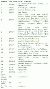
Glove Box Light; Heated Door Lock; Ignition Key Warning/Seatbelt Warning; Interior Lights; Lights:Turn/Hazard Warning; On-Boar Computer; Radio/Power Antenna; Active Check Control; Dash Lights; Front Park/Tail/Underhood Light; Rear Marker/LicenseLights; Active Check Control; Backup Lights/Transmission Range Lights; Brake Lining Warning; Cruise Control; Dash Lights; Gauges; Idle Speed Control; Interior Lights; Power Mirrors; Power Windows; Trunk Light, Fuel Delivery/Evaporative Control; Idle Speed Control, Headlights , Cigar Lighters, Active Check Control; Auto Charging Flashlight; Central Locking; Gauges; Radio/Power Antenna; Stoplights/Cruise Control; Warning Indicators, Rear Defogger/Sunroof, Automatic Heater-Air Conditioner; Auxiliary Fan; Vacuum pump, FOglights(RH), Seatbelt Warning; Speedometer; Warning Indicators, Headlights,
Mercedes Explanation Fuse Box Year Benz 2000 W211 Diagram
Fuse Box Mercedes Benz 2000 W211 Diagram


Fuse Panel Layout Diagram Parts: camshaft sprocket, washer, collar bolt, compression spring, servo magnet, armature, straight pin in camshaft, inlet camshaft, front cover, ignition control module position sensor, control plurge.
Fuse Box Ford 1997 Mondeo Mk5 Central Diagram
Fuse Box Ford 1997 Mondeo Mk5 Central Diagram


Fuse Panel Layout Diagram Parts: cigar lighter, interior lights, clock, radio, heated rear screen, sidelight, horn, alarm, central locking, electric mirror, seat height adjustment, heated front seats, central locking, electric windows, wiper motor, brake light, air bag, heated mirror, blower motor, ignition coil, direction indicator, diagnostic plug, fog light, daytime running light, daytime running light, door locking module, luggage compartment release.
Thursday, September 11, 2014
Electric Zero Voltage Switching Circuits Wiring diagram
Electric Zero Voltage Switching Circuits Diagram
Wednesday, September 10, 2014
Amplifier Circuit 2W
Amplifier description:
Amplifier circuit diagram:

Tuesday, September 9, 2014
600W Audio Amplifier Wiring diagram Schematic
Maximum Output power @ 8ohms : 300watt
Absolute max power supply voltage :±38V to ±40V
Recommended power supply voltage :±30V to ±35V
Electronic Cricket Match Game
Output from IC1 passes into the input of IC2 which is the popular Johnson Decade counter CD4017. It has 10 outputs. Of these 8 outputs are used. Output 9 ( pin9) is tied to the reset pin 15 to repeat the cycle. When the input pin 14 of IC2 gets low to high pluses, its output turns high one by one. Resistor R3 keeps the input of IC2 low in stand by state to avoid false indications.
Electronic Cricket Circuit Diagram
When the Push Switch S1 is pressed momentarily, the Astable operates and all the LEDs run very fast sequentially. When S1 is released, any one of the LED stands lit which indicates the status of the match. For example, if LED D7 remains lit, it indicates Sixer and if LED 8 remains lit, it indicates Catch out. Label each LED for its status as shown in the diagram. Pressing of S1 simulates Bowling and Running LEDs indicates running of Batsman.
Sound in the car
 It is known that for many motorists machine evolved into something more than just a means of transportation. After all, the person conducting the wheel for several hours a day, not only wants to listen to the local news, but good music. However, high-quality automotive interior equipping reproducing unit, few who can manage only industrial products.

Original article source cxem.net
