Showing posts with label watt. Show all posts

Tuesday, November 4, 2014

LM4990 2 Watt Audio Power Amplifier with Selectable Shutdown Logic Level

The LM4990 is an audio power amplifier primarily designed for demanding applications in mobile phones and other portable communication device applications. It is capable of delivering 1.25 watts of continuous average power to an 8Ω BTL load and 2 watts of continuous average power (LD and MH only) to a 4Ω BTL load with less than 1% distortion (THD+N+N) from a 5VDC power supply. Boomer audio power amplifiers were designed specifically to provide high quality output power with a minimal amount of external components. The LM4990 does not require output coupling capacitors or bootstrap capacitors, and therefore is ideally suited for mobile phone and other low voltage applications where minimal power consumption is a primary requirement.


2  2 Watt Audio Power Amplifier with Selectable Shutdown Logic Level

The LM4990 features a low-power consumption shutdown mode. To facilitate this, Shutdown may be enabled by either logic high or low depending on mode selection. Driving the shutdown mode pin either high or low enables the shutdown pin to be driven in a likewise manner to enable shutdown. The LM4990 contains advanced pop & click circuitry which eliminates noise which would otherwise occur during turn-on and turn-off transitions. The LM4990 is unity-gain stable and can be configured by external gain-setting resistors.
 Features


  • Available in space-saving packages: LLP, Exposed-DAP TSSOP, MSOP, and ITL
  • Ultra low current shutdown mode
  • Improved pop & click circuitry eliminates noise during turn-on and turn-off transitions
  • 2.2 - 5.5V operation
  • No output coupling capacitors, snubber networks or bootstrap capacitors required
  • Unity-gain stable
  • External gain configuration capability

  • User selectable shutdown High or Low logic Level
    Key Specification
    Improved PSRR at 217Hz & 1KHz  62dB
    Power Output at 5.0V, 1% THD+N, 4Ω (LD and MH only) 2W (typ)
    Power Output at 5.0V, 1% THD+N, 8Ω 1.25W (typ)
    Power Output at 3.0V, 1% THD+N, 4Ω 600mW (typ)
    Power Output at 3.0V, 1% THD+N, 8Ω 425mW (typ)
    Shutdown Current 0.1µA (typ)

    Applications

    • Mobile Phones
    • PDAs
    • Portable electronic devices
    Datasheets


    Read More..

    Wednesday, October 29, 2014

    TDA2005 Low Cost 2x20 Watt Stereo Amplifier

    This circuit is a small stereo amplifier for all suitable applications like amplifying small speakers, boxing, etc. It is also suitable for car use but before, the power supply must be choked with at least 150mH and it must give up to approximately 6 to 7 amps during the upstream performance. Appropriate heatsink for the amplifier is SK08 with a height of 50 mm (approx. 2.5 K per watt). You should drill the cooler after soldering the board to center it properly. The TDA2005 also needs not be isolated from the heat sink, since the metal mounting part of the IC is grounded.
    2x202x20You should use thermal paste to improve the heat dissipation. After the assembly , case construction is left to the builder. 100K potentiometers are used for adjusting the input volume. The potentiometers are absent in the layout. The 100K resistors need only be installed if the 100 K potentiometers are not used as shown in the layout. You should use a well designed quality transformer to get less noise. It will be another good way to use a sufficient battery to power the circuit. Keep the supply wires as short as possible. Input source should be isolated from the external noises too. It is recommended to use coaxial cable to connect the input audio.

    2x20
    2x20Technical data:
    Performance of TDA2005M: (for this circuit); At 14.4 V supply voltage: 2 x 20 watts (stereo) into 4 Ohms.
    Distortion: Approx. 0.2% at 4 Watts into 4 ohm load.
    Frequency Range: Approx. 20 Hz to 22 KHz.
    Input Sensitivity: Approx. maximum 150 mV rms. .
    Power supply: + 8 to 18 volts, approx. maximum 3.5 Amps per channel. 
    Read More..

    Thursday, October 23, 2014

    How to Create 1000 Watt Power Amplifier

    Power amplifier has up to 1000 Watt power, this circuit made one channel only so if you want to create a stereo in it must be made one again, actually this is more suitable power amplifier in use for Sound System or outdoor, so if only in use for the house I think is less suitable.
    Maybe youve seen or even have an active speaker and there is written 1500 watts PMPO (Peak Music Power Output), make no mistake this is different from Power Amplifier Active Speaker, I often dismantle such Active Speaker in it only a power with power no more than 150 watts by using the transformer 2-3 Ampere. PMPO is not a real power which is issued by the Power Amplifier, but counting all the speakers that there is, for example: if there are 5 pieces of speakers on each channel and each speaker has a power of 10 W then it is 100 W PMPO.
    1000W
    1000W Power Amplifier schematics
    1000W
    Part List 1000W amplifier


    1000W
    Speaker wiring
    Read More..

    Wednesday, September 24, 2014

    Power Inverter 1000 Watt by Mosfet

    This power inverter circuit will provide a very stable “Square Wave” Output Voltage. Frequency of operation is determined by a pot and is normally set to 60 Hz. Various “off the shelf” transformers can be used. Or Custom wind your own for best results.

    Additional MosFets can be paralleled for higher power. It is recommended to Have a “Fuse” in thePower Line and to always have a “Load connected”, while power is being applied. The Fuse should be rated at 32 volts and should be aproximately 10 Amps per 100 watts of output.

    The Power leads must be heavy enough wire to handle this High Current Draw! appropriate Heat Sinks Should be used on the RFP50N06 Fets. These Fets are rated at 50 Amps and 60 Volts. Other types ofMosfets can be substituted if you wish.

    Note
    There ARE Limitations! I have had numerous requests for an Inverter for 1000 watts and Even MORE. Sorry I Don’t feel this is Practical. At 1000 Watts and operating from a 12 Volt Source, the Input Current will be close to 100 AMPS. That would Require a HUGH Size of a Primary Wire. 

    Read More..

    Sunday, September 7, 2014

    5 8 Watt Audio Power Amplifier

    This schema use TA7222AP to amplifiers audio signal .The price only $0.99 and can provide 5.8 watt with Muting Control.Power supply can use for 8-12Vdc it is a good idea to use for car audio power amp , coin-op machine game, security system etc.


    Fig 1. TA7222AP pin out


    Pin Name Description
    1 Vcc Supply Voltage
    2 RR Ripple Reject
    3 MC Muting control
    4 OP AF Signal Input
    5 FB FB Filter
    6 GA Gain adjust
    7 GND Ground
    8 GND Ground
    9 OP AF Output
    10 BS BootStrap


    Fig 2. schematic for 5.8 watt audio power amplifier
    Read More..

    Saturday, September 6, 2014

    2 X 40 Watt STK amplifier

    STK
    Components of the above is one component of ic which is applied as a reinforcement. Power amplifier used in an audio signal in order to become more powerful and can be heard via a tool that is the speaker. But in each set must have a voice amplifier, voltage, power quality is different.
    For the IC has the output power above 2 X 40 Watt with 8 Ohm output impedance. Supply voltage ranging from 18 Volt to 32 Volt.


    STK4389
    Part List
    Resistor
    R1_____1K
    R2_____1K
    R3_____22K
    R4_____22K
    R5_____1K2
    R6_____100K
    R7_____560R
    R8_____1K
    R9_____1K
    R10____470R
    R11____4R7
    R12____3K3
    R13____3K3
    R14____4R7
    R15____470R
    R16____100R
    R17____100K
    R18____1K2

    Capacitor
    C1_____470pF
    C2_____470pF
    C3_____4u7F
    C4_____4u7F
    C5_____82pF
    C6_____82pF
    C7_____47uF
    C8_____100uF
    C9_____10nF
    C10____39pF
    C11____100nF
    C12____47uF
    C13____47uF
    C14____100nF
    C15____39pF
    C16____10nF
    C17____100uF
    C18____47uF

    Intregated Circuit
    U1_____STK4773 , STK4793 , STK4803 , STK4813 , 4833 , 4843 , 4853 , 4863 , 4873 , 4893 , 4913.
    On every IC that I mentioned has a different power output.
    Read More..

    Sunday, August 31, 2014

    TDA2005 2 X 20 Watt Power Amplifier

    This time, there is a series of audio amplifer 20W as well, but using IC TDA 2005 as a series of his base amplifier.
    The series of 2x20 Watt Audio Power Amplifier using TDA2005 can you see in the picture below.


    TDA2005


    Technical Data:

    Performance of TDA2005M: (for this circuit); At 4.14 V supply voltage: 2 x 20 watts (stereo) into 4 Ohms.
    Distortion: Approx. 0.2% at 4 Watts into 4 ohm load.

    Frequency Range: Approx. 20 Hz to 22 KHz.

    Input Sensitivity: Approx. maximum 150 mV rms. .

    Power supply: + 8 to 18 volts, approx. 3.5 Amps maximum per channel.
    Read More..

    Friday, August 29, 2014

    How to Create 1000 Watt Power Amplifier

    Power amplifier has up to 1000 Watt power, this circuit made one channel only so if you want to create a stereo in it must be made one again, actually this is more suitable power amplifier in use for Sound System or outdoor, so if only in use for the house I think is less suitable.
    Maybe youve seen or even have an active speaker and there is written 1500 watts PMPO (Peak Music Power Output), make no mistake this is different from Power Amplifier Active Speaker, I often dismantle such Active Speaker in it only a power with power no more than 150 watts by using the transformer 2-3 Ampere. PMPO is not a real power which is issued by the Power Amplifier, but counting all the speakers that there is, for example: if there are 5 pieces of speakers on each channel and each speaker has a power of 10 W then it is 100 W PMPO.
    1000W
    1000W Power Amplifier schematics
    1000W
    Part List 1000W amplifier
    While this 1000 Watt Power Amplifier minimal use transformer 20 Ampere. And the output of Power Amplifier DC voltage contains approximately 63 volts, with currents and voltages of this magnitude, this 1000 Watt Power Amplifier will not hesitate hesitate to destroy your woofer speakers to connect. To overcome that then before the speaker on connects to 1000 Watt Power Amplifier must be in pairs Speaker Protector.

    Actually if you want to create a Power Amplifier with great power does not have to make a Power Amplifier with great power. Example: you want to create a Power Amplifier with 10 000 Watt power. You do not have to assemble a Power Amplifier with power of 10,000 watts, but you assemble the power Power Amplifier Small but many, such as you assemble the Power Amplifier with 1000 Watts of power for as many as 10 pieces, it will produce 10 000 Watt Power Amplifier helpless.

    Circuit uses power transistors pair of 5 x 5 x 2SA1216 and 2SC2922 and 2SC1583 use a differential amplifier that actually contains 2 pieces of transistors that are in containers together. Why use such built-in amplifier differental tujuanya so identical / similar, could have uses 2 separate transistors but can result in amplifier so it is not symmetrical.

    Tips combining speaker.

    To get the speakers with great power combining techniques can be used in parallel series, combining each group of speakers should sepaker they will have the same impedance, the same type (Woofer, Mid Range or tweeter) and the same power. Number of merging these speakers should consists of 4 , 9, 16 ff, see picture
    1000W
    Speaker wiring


    Example: The number of speakers have 4 pieces each of its 200 Watt power generated will be a speaker at = 200 x 4 = 800 Watt. If there are 9 speakers 200 W then the result = 9 x 200 W = 1800 Watt.
    Read More..

    Monday, August 25, 2014

    14 Watt car audio amplifier circuit

    Basic operation of this amplifier is on IC TEA2021 ,

    In this circuit minimum require voltage is 4 volts and maximum voltage 25 volts. Power output 14 Watt with 4 Ohm impedance. See this schematic.
    Read More..

    Saturday, August 23, 2014

    2 X 1 8 Watt stereo low power amplifier circuit

    This is Low power amplifier , based on IC TDA2824 product of Philips. Maximum output is about 2 X 1,8 Watt , these include low  output amplifier type. Minimum required voltage 3 Volts and maximum voltage of 18 volts DC.


    Specification :
    • Supply Voltage : 3 - 18 Volts
    • Power Output   : 2 x 1,3 Watts
    • RL impedance  : 4 Ohms
    • Frequency responses : 30Hz -18kHz
    • Quiescent current : 6 mA                

    Read More..

    Wednesday, August 20, 2014

    4 X 15 Watt Mini Power Amplifier Wiring diagram Schematic

    A lot of electronic diagram in the domain of audio amplifiers are already been published here. This schema is a little different because it is a four channel amplifier. Each channel of this amplifier can deliver an output of 15Watts into a 4 ohm speaker. The amplifier can be operated from a single 12V DC supply and this makes it possible to use this amplifier in car audio applications too.

    4 X 15 Watt Mini Power Amplifier Circuit diagram :


    4X15W-amplifier-schema
    4 X 15 Watt Mini Power Amplifier

    The schema is based on the 15W BTL X 2 channel audio power amplifier IC TA8215 from Toshiba. Even though chip is specifically designed for car audio applications it can be also used for home audio applications. Two TA8215 ICs are used here in order to obtain a 4 channel amplifier system. The schema is designed almost exactly as per the application diagram in the ICs datasheet. Pins 7 and 19 are the Vcc pins of the ICs internal integrated power amplifier stages and these pins are connected to the positive supply. Pin 9 is the Vcc pin for ICs internal preamplifier and it is also connected to the positive supply. Pins 13 and 14 are the internal power amplifiers ground pins and they are tied together and connected to the ground. 

    The internal preamplifier’s ground pin (pin5) is connected to the common ground through a 10 Ohm resistor which makes the input ground separated from the common ground by a resistance of 10 ohms and this improves the noise rejection. The 100uF capacitor works as a power supply de-coupler. The resistor networks connected to the output lines of each amplifier improves the high frequency stability. The variable resistors (R3, R4, R12 and R13) works as the volume controller for the corresponding channels.

    Notes :
    • Assembling the schema on a good quality PCB is a must for obtaining optimum sound quality.
    • Use 12V DC for powering the schema.
    • The ICs must be fitted with adequately sized heat sinks.
    • R3, R4, R12 and R13 serves as volume controllers.
    • K1 to K4 can be 4 Ohm, 20W speakers.
    • This amplifier schema can be used in a variety of applications such as car audio systems, home theater systems, personal audio systems, public address systems etc.
    Read More..

    Sunday, August 17, 2014

    2 3 Watt Low audio power amplifier

    KA2202
    These amplifiers using IC KA2202 and KA2207, which has a power output of 2.3 Watt berimpedansi 4 ohms. Minimum supply voltage and maximum 5Volt 20Volt. See schematics and component list below.


    Part List 
    R1 = 100K
    R2 = 56R
    R3 = 56R
    R4 = 1R
    Use 1/4 Watt resistor
    10W

    C1 = 100uF
    C2 = 100uF
    C4 = 100uF
    C5 = 470uF
    C6 = 100nF
    C7 = 470pF
    C8 = 2,2nF
    C9 = 100uF
    U1 = KA2202 , KA2207
    Read More..

    Saturday, August 16, 2014

    Inverter 5000 Watt PWM

    This inverter uses PWM (Pulse Width Modulator) with type IC SG3524. IC serves as a oscillator 50Hz, as a regulator of the desired output voltage. Input power ranging from 250W up to 5000W output and has. Following a series INVERTER 5000W with PWM (Pulse Width Modulator).
    Inverter 5000W with PWM (Pulse Width Modulator)
    Schematic Inverter 5000W with PWM (Pulse Width Modulator)

    Inverter 5000W with PWM (Pulse Width Modulator)
    Layout PCB Inverter 5000W with PWM (Pulse Width Modulator)


    below is the output power settings that can be issued by this inverter:

    DC voltage and Transformer "T2" winding recommendation:

    Winding Power Supply

    12VDC 750W P: 24V "12-0-12" / S: 220V

    1500W 24VDC P: 48V "24-0-24" / S: 220V

    2250w 36VDC P: 72V "36-0-36" / S: 220V

    3000w 48VDC P: 96V "48-0-48" / S: 220V

    3750w 60VDC P: 120V "60-0-60" / S: 220V

    4500w 72VDC P: 144V "72-0-72" / S: 220V

    5250w 84VDC P: 168V "84-0-84" / S: 220V


    Transformer used is the transformer CT

    R1 serves to regulate the voltage to 220v inverter

    R2 serves to regulate the inverter output frequency of 50 or 60 Hz (as appropriate)

    Read More..

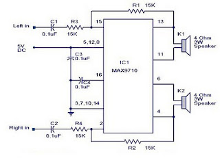
    3 Watt stereo amplifier circuit

    3 Watt stereo amplifier circuit using MAX 7910 IC. The MAX9710 a stereo audio power amplifier IC capable of delivering 3Watts of out put to 4 Ohm loads. MAX9710 can be operated from a single 4.5V to 5.5V power supply , makes it ideal for hand held applications.The IC for 3 Watt stereo amplifier circuit also features thermal overload protection.


    Circuit Schematics 3 Watt  Stereo Amplifier MAX 7910 
    3 Watt stereo amplifier circuit
    3 Watt stereo amplifier circuit 

    This 3 Watt stereo amplifier circuit  is suitable for small power audio devices such as radio sets and portable CD players. 5 V DC power supply is used for powering the 3 Watt stereo amplifier circuit. 6V battery with an IN 4007 diode series to the positive terminal of it can also be used instead of 5 V DC supply. The 3 Watt stereo amplifier circuit will get a supply voltage approximately 5 V after 0.7 V voltage drop across diode.

    Read More..