Showing posts with label with. Show all posts

Thursday, November 20, 2014

PWM Controler With Ic 555


IC Timer 555 has a basic PWM controller with pulse width control feature 0 .. 100% which is controlled using the R1, at the time of controlling the oscillator frequency relatively stabi so it may be used to build the Simple PWM controller. Frequency of Simple PWM controller 555 depending on the value of R1 and C1, values ​​shown R1 and C1 will form the output with a frequency of 170 to 200 Hz. Diode-diode used in the Simple PWM controller With this 555 can use a 1N4148.R2, R3 and C3 form a giver triger circuit beginning at the reset IC 555 for 2 seconds. If you want to use a series of Simple PWM controller 555 with the V + not +12 V, it does not matter to raise  R2 where (V + * R2) / (R2 + R3) is about 2, because it limits the signal level reset is 0.5 .. 1V. If you do not do that, then signal the kickstart to get too close to the limit reset signal reception.

Q output of 555 on the Simple PWM controller circuit 555 is used for driver PWM pulse, so that the discharge pin is used for transistor output driver instead. This is an open collector output, and is used as an active signal is low, so it can work. D3 protects the output transistor of the load induction. You may replace any suitable transistors for Q1, BD140 is 1.5 amps.

C4 and C5 is the power decoupling capacitor for the IC 555 on the Simple PWM controller circuit 555, which produce relatively large level of push-pull output stage.

Read More..

Control Relay Circuit with 9 Second

See figure below its Control Relay Circuit Schematics.

Control
Read More..

Wednesday, November 19, 2014

Stereophonic Amplifier with TDA7088T

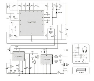
There are two signals that are directed at the so-called FM transmitterthe coder (coding). Multiplexing Mpx signal has been contained, two left signals and right indirectly. Frequency modulation of a transmitter carried by the signal Mpx. The receiver output signal is obtained on Mpx and FM detector is then passed to the decoder. At the decoder do the opposite with the coder in the transmitter, because at this level produced two signals L and D.
ic
Signal is amplified by audio amplifier dientik two, then reproduced through two speakers are the same. Now listeners can heard coming from the left half the loudspeaker is placed on the left and right half of which is placed on the right side. Situation amid the orchestra will be equal to that of the second lordspeaker reproduced, made ​​an impression on the listener as if there.

The third loudspeaker placed midway between the left and right. Based on all these listeners have a picture of the layout space, which is significantly increased total musical impression. Electronic circuits of the portable stereophonic radio receiver with headphones reproduction, made ​​by the IC TDA 7088T is shown in Figure the above. This is a practical embodiment of the receiver with TDA7040T decoder and two audio amplifier with TDA7050T IC.

Choke (coils) L3, L4 and L5 are HF coil allows the headphone cable is used as a receiving antenna. this fulfilled by connecting one contact of the plug-in headphones, through a 10 pF capacitor at the point where the output of the antenna is connected. Coil has a significant barrier to the signal station, preventing ground connection through capacitor 47 mF or through the TDA7050T output.
Read More..

Tuesday, November 11, 2014

78L05 7805 based 5V regulator circuit with explanation

This is a very simple article, just trying to help ….
What is the most vital piece we always need in electronics? The answer is …. a good power supply, right? :D .
The best regulators for using in electronic projects are the 78LXX (78L05, 78L09, 78L12, 78L15 … ). I searched google for the application notes and I found them easily (look in the bottom part of the page for the download link).
Their typical application was the IC + 2 small condensers (the input is at 0.33uF and the output is at 0.01uF), but after some tryouts and more googling I found this page which, too be honest with you, I consider it to be the best circuit over the web.
I tested the circuit and it worked like charmed.
Reading the application note we see that the input voltage must be between 7V and 20V and the output voltage is between 4.75V – 5.25V
Components:
  • IC1 = 78L05 / 7805
  • D1 = 1N4007
  • C1 = 100uF
  • C2 = 10uF
Bibliography :
  • http://www.pmb.co.nz/psu_general_1.htm
  • http://www.national.com – The official manufacturer page
  • The 78L05 Datasheet : http://www.national.com/ds/LM/LM78L05.pdf
Read More..

Saturday, November 8, 2014

Cable TV amplifier With 2 Transistors

This is a actual simple cable TV amplifier application two transistors. This amplifier ambit is a lot of acceptable for cable TV systems application 75 Ohm coaxial cables and works accomplished up to 150MHz. Transistor T1 performs the job of amplification. Up to 20dB accretion can be accepted from the circuit.T2 is active as an emitter addict to access accepted gain.

Notes.
  • The circuit can be assembled on a Vero board.
  • Use 12V DC for powering the circuit.
  • Type no of the transistors are not very critical.
  • Any medium power NPN RF transistors can be used in place of T1 and T2.
  • This is just an elementary circuit. Do not compare it with high quality Cable TV amplifiers available in the market.
Read More..

Tuesday, November 4, 2014

LM4990 2 Watt Audio Power Amplifier with Selectable Shutdown Logic Level

The LM4990 is an audio power amplifier primarily designed for demanding applications in mobile phones and other portable communication device applications. It is capable of delivering 1.25 watts of continuous average power to an 8Ω BTL load and 2 watts of continuous average power (LD and MH only) to a 4Ω BTL load with less than 1% distortion (THD+N+N) from a 5VDC power supply. Boomer audio power amplifiers were designed specifically to provide high quality output power with a minimal amount of external components. The LM4990 does not require output coupling capacitors or bootstrap capacitors, and therefore is ideally suited for mobile phone and other low voltage applications where minimal power consumption is a primary requirement.


2  2 Watt Audio Power Amplifier with Selectable Shutdown Logic Level

The LM4990 features a low-power consumption shutdown mode. To facilitate this, Shutdown may be enabled by either logic high or low depending on mode selection. Driving the shutdown mode pin either high or low enables the shutdown pin to be driven in a likewise manner to enable shutdown. The LM4990 contains advanced pop & click circuitry which eliminates noise which would otherwise occur during turn-on and turn-off transitions. The LM4990 is unity-gain stable and can be configured by external gain-setting resistors.
 Features


  • Available in space-saving packages: LLP, Exposed-DAP TSSOP, MSOP, and ITL
  • Ultra low current shutdown mode
  • Improved pop & click circuitry eliminates noise during turn-on and turn-off transitions
  • 2.2 - 5.5V operation
  • No output coupling capacitors, snubber networks or bootstrap capacitors required
  • Unity-gain stable
  • External gain configuration capability

  • User selectable shutdown High or Low logic Level
    Key Specification
    Improved PSRR at 217Hz & 1KHz  62dB
    Power Output at 5.0V, 1% THD+N, 4Ω (LD and MH only) 2W (typ)
    Power Output at 5.0V, 1% THD+N, 8Ω 1.25W (typ)
    Power Output at 3.0V, 1% THD+N, 4Ω 600mW (typ)
    Power Output at 3.0V, 1% THD+N, 8Ω 425mW (typ)
    Shutdown Current 0.1µA (typ)

    Applications

    • Mobile Phones
    • PDAs
    • Portable electronic devices
    Datasheets


    Read More..

    Friday, October 31, 2014

    5 3W Amplifier With Surround System Diagram Circuit

    The AN7147 Dual 5.3-watt Audio Power Amplifier from Panasonic is listed as a ‘replacement type’ so hopefully will be around for some time to come. Together with some extra components, it can represent a simple surround-sound system requiring no opamps or a negative voltage supply. As shown by the circuit diagram the basic stereo amplifier is changed into a surround-sound system by a trick called ‘adding feedback from the opposite channel’. When surround sound is required, the negative feedback signals supplied by C13-R3 and C12-R4 are fed to the inputs of the ‘other’ amplifier. The resulting phase difference causes the surround effect. If surround sound is not required, the effect can be disabled by pressing push-button S1.

    5.3W
    This causes the bistable built around IC2.A and IC2.B to toggle and drive transistors T1 and T2 such that the above mentioned negative feedback signals are effectively shunted to ground. A high-efficiency LED and a 3.3-kΩ series resistor (R14) should be used to make sure the maximum output current of the CMOS 4001 device is not exceeded. The amplifier should not be loaded with impedances smaller than 3Ω. The AN7147 will typically supply up to 4.3 watts into 4 Ω. The SIL-12 case needs to be cooled wit a small heatsink of about 6 K/W or better. The quiescent current is modest at just 19 mA.
    Read More..

    Thursday, October 30, 2014

    1HZ Standard digital clock circuit with explanation

    1HZ
    This is a standard digital clock circuit,frequency size 1 Hz or 2 Hz. It can be used in the normal clock circuit. It consists of IC-4060 and IC-4013, the IC-4060 single acting Oscillator and Counter. of the frequency determined by the resistor and external capacitor.In the circuit, IC 4060 is a standard frequency generator with quartz crystal. The adjustment period with C2, and counter circuits within the IC 4060 will be only 2 Hz frequency dividing out the pin 3. The IC-4015 in the style of TF / F to divide two of the Clock signal frequency is out 1 Hz.
    Read More..

    Wednesday, October 29, 2014

    STK4050 Audio Amplifier with 200W

    Overview
    The project is based around the hybrid integrated circuit STK4050 manufactured by Sanyo to build a low noise mono audio amplifier with complete high quality.
    Explanation The project has a maximum output power of 200W while incorporating a volume control. The power supply used in the circuit is an on-board type and because of this, only a center tapped transformer is needed for the powering of the circuit. The sound has a very good quality and it can be proven when used in home theaters, in computers, and other audio equipments which can also be used as subwoofer amplifier.
    For thin-type audio sets, it can be considered as a compact package. The heat generated in thin-type audio sets is being dispersed easily with a good heatsink design. There may be case where a shock noise may be encountered especially during switch ON and switch OFF. This can be reduced by providing a constant current circuit. The design of the circuit can be tailored for reducing occurrence of thermal shutdown, short circuit protection for loads, shock noise muting from external power supply.
    The load resistance should have 8 Ohms value with 55K Ohms input impedance.


     Modifikasi STK 4050

    Read More..

    Tuesday, October 28, 2014

    500W Power Amplifier with 2SC2922 2SA1216

    This amplifier has Output power about 500 Watt with the compatible voltage supply is under 63 Volt or same. If this amplifier operated the transistor output recomended to be place on the good heatsink. Because, the transistor will be hot. Transistor Ouput using SANKEN 2SC2922 and 2SA1216. Below describe the Circuit Diagram of 500W Power Amplifier :

    500W

    Could you repeat that? can occur made to add to offered audio power amplifier? The answer is either decrease load impedance otherwise increase supply voltage. The drop the impedance, the extra current is wanted, making the construction of low impedance output stages other testing (at hand are selected other matter-of-fact limits), so consent tos increase supply voltage.

    Sanken
    Sanken Transistor 2SC2922 [NPN] and 2SA1216 [PNP]
    Components/parts list : 
    R1,R11  47K
    R2,R3 33K
    R4 1K5
    R5,R7 2K2
    R6,R8 100R
    R9,R10 56R
    R12 820R
    R13 10R/5W

    C1 220nF
    C2,C3,C4 100uF/100V
    C5,C6 100pF
    C7 100nF/100V

    D1,D2 IN4002

    TR1,TR2 D438
    TR3,TR4 B560
    TR5,TR8 A958
    TR6,TR7 C2168
    TR9,TR10 2SC2922
    TR11,TR12 2SA1216
    Read More..

    Wednesday, October 15, 2014

    Build a 25W Bridge Audio Amplifier with TDA2005

    This is the 25W bridge audio amplifier built using single power IC TDA2005. Actually, the TDA2005 is a stereo power amplifier chip. It has two input channels and two output channel and delivers about 10W power output for each channel, since it connected in bridge mode then it will delivering up to 25W audio output. Take a note that the speaker terminals should not conected to the ground and mount the IC on the heatsink to prevent overheating.

     25W Bridge Audio Amplifier with TDA2005 Circuit Diagram

     
    Parts List:
    R1 = 120K?
    R2,5,6 = 1K?
    R3,4 = 12?
    R7,8= 1?
    C1,5,7 = 220uF/25V
    C2,10,11 = 100nF
    C3,4 = 2.2uF/25V
    C6,8 = 100uF/25V
    C9 = 10uF/25V
    IC1 = LM2005M / TDA2005
    Read More..

    Friday, October 3, 2014

    20W Bridge Amplifier with TDA2005


    TDA2005 is a 20W amplifier is a bridge to the car radio. The TDA 2005 is ClassB dual audio power amplifier in MULTIWATT) package specifically designed for car radio applications: power booster amplifiers are easily designed with this device that provides a high current capability (up to 3.5 A) and that can handle very low impedance loads (up to 1.6 W).

    TDA2005M is designed to bridge TDA2005S applications for music application. With TDA 2005S can build a 2 x 10watt stereo amplifier circuit 2 x 2Ω speakers with 10% distortion.

    TDA 2005 maximum ratings

    Operating Supply Voltage 18 V
    DC Supply Voltage 28 V
    Peak Supply Voltage (for 50 ms) 40 V
    Output Peak Current (non repetitive t = 0.1 ms) 4.5 A
    Output Peak Current (repetitive f . 10 Hz) 3.5 A
    Power Dissipation at Tcase = 60 °C 30 W
    Storage and Junction Temperature – 40 to 150 °C
    Read More..

    Saturday, September 6, 2014

    High and quality audio power amplifier with MJ15024G and MJ15025G

    Spesification of this amplifier is high enough , and require a lot of expense to make this super-power amplifier. In the transformer using 20A and manufactered / branded ERA , ERA trafo is one of the best transformer , in addition to the power amplifier as well as power supply adapter , regulator , stabilizer , charger , etc. Because copper is intact , a strong iron and did not issue a frequency so that when the amplifier is turned on , output sound amplifier no buzzing. So if you in choosing a transformer , do not hesitate to use the transformer branded ERA.
    hightransistor 
    Above and below the picture is the end of the amplifier circuit, so-called booster amplifier. Picture above using 14 pairs of transistor MJ15025G and his partner MJ15024G . Transistor price range of $5 - $6 , has power output of 250W on each transistor , for more details , see datasheet of each transistor.
    Click to view larger
    Installed transistor with resistor but still a mess
    Transistors MJ5025G and MJ15024G very fith with power amplifier 300 Watt subwoofer , 450 Watt , 600W , 750 Watt , 1050 Watt , 1200 Watt , and higher. The buffer and its driver using transistor not ic. For power schematic diagram can be found here.
    Read More..

    Friday, September 5, 2014

    Bass Booster with TL072

    The following is megabass circuit schematic (rangkaian megabass) . The megabass circuit is a modified Baxandall tone control with no bass cut and no treble control. It boosts frequencies from about 30Hz to 160Hz can boost by 14dB.

    Bass Booster Schematics
    Bass

    Note:
    The input capacitor can be replaced with a .01uf cap if you wish.
    The 10pf capacitor is optional and will start rolling off everything over 15kHz. 5pf will double this to 31kHz.
    The tone control requires a low impedence input. If you already have a low impedence input, the input buffer can be removed. However, the output is inverted.
    The opamp is not critical. A 4558 would be just fine.
    I do not show the parts for the +4.5 reference. Here is the +4.5 voltage divider I used.
    IC A4558 Pinning

    The A4558 is a monolithic Integrated Circuit designed for dual operational amplifier.

    Absolute maximum ratings of A4558 Ap-amp
    Supply voltage VCC 20 or ±10 V
    Differential input voltage VIND 20 V
    Input voltage VIN ±10 V
    Power Dissipation PD 300 mW
    Operating temperature Topr -45 ~ +85 °C
    Storage temperature Tstg -55 ~ +150 °C
    Read More..

    Wednesday, September 3, 2014

    Doorbell with IC555

    Doorbell
    All components arranged as in the picture sequence below. Current will flow starting from the source voltage and to the switch. When the switch is closed current will flow through the diode, where diode serves as a switch is closed because it was given forward bias (anode diode is given positive voltage and the cathode is given a negative voltage).
    Read more
    Read More..

    Monday, September 1, 2014

    Line Follower Robot with AVR ATMega8535

    Line Follower Robot with AVR ATMega8535 - Make the robot line follower is exciting, especially for those who like to friends experimented with AVR microcontroller ATMega. "Line Follower Robot" is a robot designed to follow the trail (can be a line putus2 line or even a point to point). Creating a Line Follower Robot uses an AVR microcontroller ATMega 8535 is very possible and very reliable. Due to the design of a Line Follower Robot should we think that the trail will be followed step by step Line Follower Robot will be made to track or path in Line Follower Robot is passed. And of the Line Follower Robot needs tersbut feature2 owned by AVR microcontroller ATMega 8535 is sufficient and meets the needs of the Line Follower Robot. Line Follower Robot in the article with AVR ATMega8535 I made a simple graffiti to be possessed by a Line Follower Robot.

    Line Follower Robot Block Diagram of the AVR ATMega8535

    Block
    Block Diagram of Line Follower Robot with AVR ATMega 8535


    Function Block Diagram of Line Follower Robot with AVR ATMega 8535 :
    1. Line Follower Robot Sensor on can use a photo diode or photo transistor, this section serves to detect the presence of trajectory track.
    2. Keypad, this part of the function buttons to start / stop Line Follower Robot and as voters Line Follower Robot configuration settings for the field will be going through.
    3. Display, a part which serves to show the option of setting and the setting (it is enough that needs to be in view) of this section or the viewer can use a 7 segment LCD.
    4. Motor Driver, this part of a series of H Bridge DC motor driver. This section controls the motor in langsun. This section is an AVR microcontroller interface anatara ATMega with DC motor. I like to use the IC motor driver L298 family.
    5. ATMega8535 AVR microcontrollers, this section is the part that determines where the robot will be taken based on the data from the sensor. This section is set langkah2 Line Follower Robot in the conquest of the track.
    ××××Creating a Line Follower Robot  ××××


    Read More..

    Surround Amplifier Circuit with TDA7053

    Perhaps the surround amplifier circuit below is an interesting circuit is made. For, making easy just by using the IC and electrolytic capacitor added 1 , we already can hear the strains of music with sound ( Front Left ,Right and surround Right , Left. In addition to listening to music , this amplifier is also very suitable for gamers who want good sound quality. Minimum voltage requred 9 volts and maximum of 15 volts. Power Output of each speaker 10 Watt with 4 ohm impedance.

    Surround Amplifier Circuit with TDA7053

    Read More..

    10 000x With One Transistor

    For a collector follower with emitter resistor, you’ll often find that the gain per stage is no more than 10 to 50 times. The gain increases when the emitter resistor is omitted. Unfortunately, the distortion also increases. With a ubiquitous transistor such as the BC547B, the gain of the transistor is roughly equal to 40 times the collector current (Ic), provided the collector current is less than a few milliamps. This value is in theory equal to the expression q/KT, where q is the charge of the electron, K is Boltzmann’s constant and T is the temperature in Kelvin.

    For simplicity, and assuming room temperature, we round this value to 40. For a single stage amplifier schema with grounded emitter it holds that the gain Uout /Uin (for AC voltage) is in theory equal to SRc. As we observed before, the slope S is about 40Ic. From this follows that the gain is approximately equal to 40I cRc. What does this mean? In the first instance this leads to a very practical rule of thumb: that gain of a grounded emitter schema amounts to 40·I c·Rc, which is equal to 40 times the voltage across the collector resistor.

    If Ub is, for example, equal to 12 V and the collector is set to 5V, then we know, irrespective of the values of the resistors that the gain will be about 40R(12–5) = 280. Notable is the fact that in this way the gain can be very high in theory, by selecting a high power supply voltage. Such a voltage could be obtained from an isolating transformer from the mains. An isolating transformer can be made by connecting the secondaries of two transformers together, which results in a galvanically isolated mains voltage.


    10,000x

    10,000x With One Transistor Circuit diagram

    That means, that with a mains voltage of 240 Veff there will be about 340 V DC after rectification and filtering. If in the amplifier schema the power supply voltage is now 340 V and the collector voltage is 2 V, then the gain is in theory equal to 40 x (340–2). This is more than 13,500 times! However, there are a few drawbacks in practice. This is related to the output characteristic of the transistor. In practice, it turns out that the transistor does actually have an output resistor between collector and emitter.

    This output resistance exists as a transistor parameter and is called ‘hoe’. In normal designs this parameter is of no consequence because it has no noticeable effect if the collector resistor is not large. When powering the amplifier from 340 V and setting the collector current to 1 mA, the collector resistor will have a value of 338 k. Whether the ‘hoe’-parameter has any influence depends in the type of transistor. We also note that with such high gains, the base-collector capacitance in particular will start to play a role.

    As a consequence the input frequency may not be too high. For a higher bandwidth we will have to use a transistor with small Cbc, such as a BF494 or perhaps even an SHF transistor such as a BFR91A. We will have to adjust the value of the base resistor to the new hfe. The author has carried out measurements with a BC547B at a power supply voltage of 30 V. A value of 2 V was chosen for the collector voltage. Measurements confirm the rule of thumb. The gain was more than 1,000 times and the effects of ‘hoe’ and the base-collector capacitance were not noticeable because of the now much smaller collector resistor.
    Author: Gert Baars
    Read More..

    Sunday, August 31, 2014

    Stereophonic circuit with TDA7088T

    There are two signals that are directed at the so-called FM transmitterthe coder (coding). Multiplexing Mpx signal has been contained, two left signals and right indirectly. Frequency modulation of a transmitter carried by the signal Mpx. The receiver output signal is obtained on Mpx and FM detector is then passed to the decoder. At the decoder do the opposite with the coder in the transmitter, because at this level produced two signals L and D.
    ic

    Signal is amplified by audio amplifier dientik two, then reproduced through two speakers are the same. Now listeners can heard coming from the left half the loudspeaker is placed on the left and right half of which is placed on the right side. Situation amid the orchestra will be equal to that of the second lordspeaker reproduced, made ​​an impression on the listener as if there.

    The third loudspeaker placed midway between the left and right. Based on all these listeners have a picture of the layout space, which is significantly increased total musical impression. Electronic circuits of the portable stereophonic radio receiver with headphones reproduction, made ​​by the IC TDA 7088T is shown in Figure the above. This is a practical embodiment of the receiver with TDA7040T decoder and two audio amplifier with TDA7050T IC.

    Choke (coils) L3, L4 and L5 are HF coil allows the headphone cable is used as a receiving antenna. this fulfilled by connecting one contact of the plug-in headphones, through a 10 pF capacitor at the point where the output of the antenna is connected. Coil has a significant barrier to the signal station, preventing ground connection through capacitor 47 mF or through the TDA7050T output.
    Read More..

    Thursday, August 28, 2014

    Toggle switch with Infra Red IR

    Toggle switch in this article is a series of toggle switches that are controlled by infrared light. The series toggle switch is made from a combination of data flip-flop CD4013 2 units.
    Read more
    Read More..