Showing posts with label amplifier. Show all posts

Wednesday, November 19, 2014

45 W Stereo Tube Amplifier

Stereo Amplifier with Tube
Stereo amplifier is very simple, consisting of 5 active components including the power supply it. Series Stereo Amplifier With Tube was prepared with 5 units trioda tube consisting of 1 unit tubes 5Y3 GT vacuum rectifier, 2 tube tube trioda 6SF5 GT high-mu tube 6k6 and 2 units which form the power beam amplifiers.


Power consumption for the circuit with a tube stereo amplifier is not more than 45 Watt. Current consumption for the circuit with a tube stereo amplifier is around 3A. A complete range of stereo amplifiers with this tube can be seen from the following series of images.

Stereo Amplifier With Tube


Sign Component Stereo Amplifier With Tube
  • R1, R10, R13 2.2M
  • R2 470K 1/2W
  • 1 Meg 1/2W R3
  • R4 220K 1/2W
  • R5 330 Ohm 2W
  • R6 220K 1/2W
  • R7 2.2Meg 1/2W
  • R8 1Meg 1/2W
  • R9 720 Ohm 20W
  • R11 33K 1/2W
  • R12 22K 1/2W
  • C1, C9 400V 0.005uF
  • C2 0.05uF 600V
  • C3 20uF 25V
  • C4 0.01uF 400V
  • C5 200uuF 400V
  • C6, C7 15uF 450V
  • C8 15uF 400V
  • T1 117V Primary, Secondary 350VCT, 2 × 6.3V
  • T2 7600 Ohm Primary, Secondary 4 or 8 Ohm
  • SW1 SPST Switch
  • SP1, SP2 12 "4 / 8 ohm
  • C8 in the series stereo tube amplifier with the above serves to reduce radio frequency interference and to optimize the work of a wild series of ampifier stereo with these tubes.
Read More..

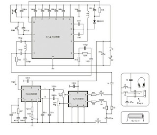
Stereophonic Amplifier with TDA7088T

There are two signals that are directed at the so-called FM transmitterthe coder (coding). Multiplexing Mpx signal has been contained, two left signals and right indirectly. Frequency modulation of a transmitter carried by the signal Mpx. The receiver output signal is obtained on Mpx and FM detector is then passed to the decoder. At the decoder do the opposite with the coder in the transmitter, because at this level produced two signals L and D.
ic
Signal is amplified by audio amplifier dientik two, then reproduced through two speakers are the same. Now listeners can heard coming from the left half the loudspeaker is placed on the left and right half of which is placed on the right side. Situation amid the orchestra will be equal to that of the second lordspeaker reproduced, made ​​an impression on the listener as if there.

The third loudspeaker placed midway between the left and right. Based on all these listeners have a picture of the layout space, which is significantly increased total musical impression. Electronic circuits of the portable stereophonic radio receiver with headphones reproduction, made ​​by the IC TDA 7088T is shown in Figure the above. This is a practical embodiment of the receiver with TDA7040T decoder and two audio amplifier with TDA7050T IC.

Choke (coils) L3, L4 and L5 are HF coil allows the headphone cable is used as a receiving antenna. this fulfilled by connecting one contact of the plug-in headphones, through a 10 pF capacitor at the point where the output of the antenna is connected. Coil has a significant barrier to the signal station, preventing ground connection through capacitor 47 mF or through the TDA7050T output.
Read More..

Friday, November 14, 2014

TDA1554 22W Stereo Amplifier Diagram Circuit

Here is the 22 watt stereo audio power amplifier circuit diagram based on TDA1554 and integrated circuit from NXP semiconductors (formerly PHILIPS semiconductors). It is very simple and useful circuit for amplify the stereo signals .The circuit dissipates roughly 28 watts of heat, so a good heatsink is necessary. The chip should run cool enough to touch with the proper heatsink installed .the circuit operates at 12 Volts at about 5 Amps at full volume. Lower volumes use less current, and therefore produce less heat. R1 is also a 5% resistor.Circuit diagram:
22W Stereo Audio Amplifier Circuit Diagram
Read More..

Saturday, November 8, 2014

Cable TV amplifier With 2 Transistors

This is a actual simple cable TV amplifier application two transistors. This amplifier ambit is a lot of acceptable for cable TV systems application 75 Ohm coaxial cables and works accomplished up to 150MHz. Transistor T1 performs the job of amplification. Up to 20dB accretion can be accepted from the circuit.T2 is active as an emitter addict to access accepted gain.

Notes.
  • The circuit can be assembled on a Vero board.
  • Use 12V DC for powering the circuit.
  • Type no of the transistors are not very critical.
  • Any medium power NPN RF transistors can be used in place of T1 and T2.
  • This is just an elementary circuit. Do not compare it with high quality Cable TV amplifiers available in the market.
Read More..

Friday, November 7, 2014

BA5406 Stereo Amplifier Circuit

In the circuit diagram shown, BA5406 is configures to deliver 5×2 watts into 4 ohm loudspeakers at a supply offer voltage of 9 volts. Capacitor C3 is a power supply filter capacitor. C11 and C12 are input DC decoupling capacitors for the left and right channels. C3 and R2 forms a Zobel network for the left output whereas C6 & R3 forms identical for the correct channel.

Purpose of the Zobel network is to cut back oscillations and improve high frequency stability of the amplifier. Potentiometers R5 and R6 serves as the quantity control for the left and right channels. CapacitorsC4 and C8 couple the outputs of the amplifier to the speakers. C9 and C10 are noise filtering capacitors. C1 and C5 are bootstrap capacitors for the left and right channels.
Read More..

Wednesday, November 5, 2014

Automatic Switch For Audio Power Amplifier

Automatic Switch For Audio Power Amplifier. Circuit of an automatic switch for audio power amplifier stage is presented here. The circuit uses stereo preamplifier output to detect the presence of audio to switch the audio power amplifier on only when audio is present.

The circuit thus helps curtail power wastage. IC1 is used as an inverting adder. The input signals from left and right channels are combined to form a common signal for IC2, which is used as an open loop comparator. IC3 (NE556) is a dual timer. Its second section, i.e., IC3(b), is configured as monostable multivibrator. Output of IC3(b) is used to switch the power amplifier on or off through a Darlington pair formed by transistors T1 and T2. IC3(a) is used to trigger the monostable multivibrator whenever an input signal is sensed.

Switch For Audio Power Amplifier Circuit Diagram:

Amplifier-Circuit-Diagram

Under ‘no signal’ condition, pin 3 of IC2 is negative with respect to its pin 2. Hence the output of IC2 is low and as a result output of IC3(a) is high. Since there is no trigger at pin 8 of IC3(b), the output of IC3(b) will be low and the amplifier will be off. When an input singal is applied to IC1, IC2 converts the inverted sum of the input signals into a rectangular waveform by comparing it with a constant voltage which can be controlled by varying potentiometer VR1. When the output of IC2 is high, output pin 5 of IC3 goes low, thus triggering the monostable multivibrator. As soon as the audio input to IC1 stops, pin 5 of IC3 goes high and pin 1 of IC3 discharges through capacitor C3, thus resetting the monostable multivibrator.

Hence, as long as input signals are applied, the amplifier remains ‘on.’ When the input signals are removed, i.e., when signal level is zero, the amplifier switches off after the mono flip-flop delay period determined by the values of resistor R8 and capacitor C3. If no input signals are sensed within this time, the amplifier turns off—else it remains on. Power supply for the circuit can be obtained from the power supply of the amplifier. Hence, the circuit can be permanently fitted in the amplifier box itself. The main switch of the amplifier should be always kept on. Resistors R1 and R2 are used to divide single voltage supply into two equal parts.

Capacitors C1 and C2 are used as regulators and also as an AC bypass for input signals. Diode D1 is used so that loading fluctuations in power amplifier do not affect circuit regulation. Transisitor T2 acts as a high voltage switch which may be replaced by any other high voltage switching transistor satisfying amplifier current requirements. Value of resistor R10 should be modified for large current requirement. The LED glows when the amplifier is on. The circuit is very useful and relieves one from putting the amplifier on and off every time one plays a cassette or radio etc. 


Read More..

Tuesday, November 4, 2014

LM4990 2 Watt Audio Power Amplifier with Selectable Shutdown Logic Level

The LM4990 is an audio power amplifier primarily designed for demanding applications in mobile phones and other portable communication device applications. It is capable of delivering 1.25 watts of continuous average power to an 8Ω BTL load and 2 watts of continuous average power (LD and MH only) to a 4Ω BTL load with less than 1% distortion (THD+N+N) from a 5VDC power supply. Boomer audio power amplifiers were designed specifically to provide high quality output power with a minimal amount of external components. The LM4990 does not require output coupling capacitors or bootstrap capacitors, and therefore is ideally suited for mobile phone and other low voltage applications where minimal power consumption is a primary requirement.


2  2 Watt Audio Power Amplifier with Selectable Shutdown Logic Level

The LM4990 features a low-power consumption shutdown mode. To facilitate this, Shutdown may be enabled by either logic high or low depending on mode selection. Driving the shutdown mode pin either high or low enables the shutdown pin to be driven in a likewise manner to enable shutdown. The LM4990 contains advanced pop & click circuitry which eliminates noise which would otherwise occur during turn-on and turn-off transitions. The LM4990 is unity-gain stable and can be configured by external gain-setting resistors.
 Features


  • Available in space-saving packages: LLP, Exposed-DAP TSSOP, MSOP, and ITL
  • Ultra low current shutdown mode
  • Improved pop & click circuitry eliminates noise during turn-on and turn-off transitions
  • 2.2 - 5.5V operation
  • No output coupling capacitors, snubber networks or bootstrap capacitors required
  • Unity-gain stable
  • External gain configuration capability

  • User selectable shutdown High or Low logic Level
    Key Specification
    Improved PSRR at 217Hz & 1KHz  62dB
    Power Output at 5.0V, 1% THD+N, 4Ω (LD and MH only) 2W (typ)
    Power Output at 5.0V, 1% THD+N, 8Ω 1.25W (typ)
    Power Output at 3.0V, 1% THD+N, 4Ω 600mW (typ)
    Power Output at 3.0V, 1% THD+N, 8Ω 425mW (typ)
    Shutdown Current 0.1µA (typ)

    Applications

    • Mobile Phones
    • PDAs
    • Portable electronic devices
    Datasheets


    Read More..

    Monday, November 3, 2014

    14W AUDIO AMPLIFIER TDA2030 ELECTRONIC DIAGRAM

    14W AUDIO AMPLIFIER TDA2030 ELECTRONIC DIAGRAM

    The values of R5 and C8 are worked out from the equations in the datasheet, but I used 1.8k ohm for R5 and 220pF for C8 and they work fine. Diodes should be 1N4001 or similar (make sure you solder them in the right way round).

    A good heatsink is important and this should be a large size with good thermal conductivity. When you operate the TDA2030 from the (recommended) split rail power supply, you must insulate the device from the heatsink using a mica washer or similar. With single rail supply, this is not needed.
    Read More..

    Saturday, November 1, 2014

    Powerful high quality amplifier

    Nmos350 Mk2
    This revised version yet to be built improves a few perfomance areas. I considered more complex ideas but this increased the component count and original idea of the amp would have been lost; that is a powerful high quality amplifier that used commonly available and cheap components.
    • A LED as the voltage reference for the first stage constant current source tracks changes in temperature slightly better that than the old double diode setup.
    • A cascode second stage makes it faster and more linear.
    • Better clipping attributes
    • The fuse has been shifted out of the voltage drive loop between the driver and output stages.

    powerful

    Nmos350 Mk2 Schematic

    Read More..

    Friday, October 31, 2014

    5 3W Amplifier With Surround System Diagram Circuit

    The AN7147 Dual 5.3-watt Audio Power Amplifier from Panasonic is listed as a ‘replacement type’ so hopefully will be around for some time to come. Together with some extra components, it can represent a simple surround-sound system requiring no opamps or a negative voltage supply. As shown by the circuit diagram the basic stereo amplifier is changed into a surround-sound system by a trick called ‘adding feedback from the opposite channel’. When surround sound is required, the negative feedback signals supplied by C13-R3 and C12-R4 are fed to the inputs of the ‘other’ amplifier. The resulting phase difference causes the surround effect. If surround sound is not required, the effect can be disabled by pressing push-button S1.

    5.3W
    This causes the bistable built around IC2.A and IC2.B to toggle and drive transistors T1 and T2 such that the above mentioned negative feedback signals are effectively shunted to ground. A high-efficiency LED and a 3.3-kΩ series resistor (R14) should be used to make sure the maximum output current of the CMOS 4001 device is not exceeded. The amplifier should not be loaded with impedances smaller than 3Ω. The AN7147 will typically supply up to 4.3 watts into 4 Ω. The SIL-12 case needs to be cooled wit a small heatsink of about 6 K/W or better. The quiescent current is modest at just 19 mA.
    Read More..

    Wednesday, October 29, 2014

    TDA2005 Low Cost 2x20 Watt Stereo Amplifier

    This circuit is a small stereo amplifier for all suitable applications like amplifying small speakers, boxing, etc. It is also suitable for car use but before, the power supply must be choked with at least 150mH and it must give up to approximately 6 to 7 amps during the upstream performance. Appropriate heatsink for the amplifier is SK08 with a height of 50 mm (approx. 2.5 K per watt). You should drill the cooler after soldering the board to center it properly. The TDA2005 also needs not be isolated from the heat sink, since the metal mounting part of the IC is grounded.
    2x202x20You should use thermal paste to improve the heat dissipation. After the assembly , case construction is left to the builder. 100K potentiometers are used for adjusting the input volume. The potentiometers are absent in the layout. The 100K resistors need only be installed if the 100 K potentiometers are not used as shown in the layout. You should use a well designed quality transformer to get less noise. It will be another good way to use a sufficient battery to power the circuit. Keep the supply wires as short as possible. Input source should be isolated from the external noises too. It is recommended to use coaxial cable to connect the input audio.

    2x20
    2x20Technical data:
    Performance of TDA2005M: (for this circuit); At 14.4 V supply voltage: 2 x 20 watts (stereo) into 4 Ohms.
    Distortion: Approx. 0.2% at 4 Watts into 4 ohm load.
    Frequency Range: Approx. 20 Hz to 22 KHz.
    Input Sensitivity: Approx. maximum 150 mV rms. .
    Power supply: + 8 to 18 volts, approx. maximum 3.5 Amps per channel. 
    Read More..

    STK4050 Audio Amplifier with 200W

    Overview
    The project is based around the hybrid integrated circuit STK4050 manufactured by Sanyo to build a low noise mono audio amplifier with complete high quality.
    Explanation The project has a maximum output power of 200W while incorporating a volume control. The power supply used in the circuit is an on-board type and because of this, only a center tapped transformer is needed for the powering of the circuit. The sound has a very good quality and it can be proven when used in home theaters, in computers, and other audio equipments which can also be used as subwoofer amplifier.
    For thin-type audio sets, it can be considered as a compact package. The heat generated in thin-type audio sets is being dispersed easily with a good heatsink design. There may be case where a shock noise may be encountered especially during switch ON and switch OFF. This can be reduced by providing a constant current circuit. The design of the circuit can be tailored for reducing occurrence of thermal shutdown, short circuit protection for loads, shock noise muting from external power supply.
    The load resistance should have 8 Ohms value with 55K Ohms input impedance.


     Modifikasi STK 4050

    Read More..

    Tuesday, October 28, 2014

    Low Noise Power Amplifier


    The Curiously Low Noise Amplifier takes benefit of the wonderful blast characteristics of the 2SK170 JFET to facilitate boasts a clamor voltage underneath 1 nV/burrow-Hz and practically rejection racket current. The noise voltage of the amplifier is just 1.4 nV/root-Hz by the side of 1 kHz, increasing to only 2.7 nV/delve-Hz by 10 Hz. The blare current is awkward to quantity, so this undemanding benefit amplifier can notice the clamor from a 50 ohm resistor and a 100k resistor, too. (The 1.4 nV input-referred clamor command rise to re 1.7 nV with a 50 ohm resistor, as an alternative of a sharply, and a 100k resistor will bequeath an input-referred racket approaching 40 nV, with very small contribution from the amplifier.)

    This amplifier is a "service" amplifier with a secure of 100, with the purpose of would typically occur used at home a lab setting to boost tiny signals on behalf of measurement or else added doling out. It isnt intended to drive a spokesperson or else headphones in a straight line. (It may well drive the LM386 quite nicely.) The circuit is a minimal discrete transistor view circuit with two grow stages and a unique panache-A output buffer stage:

    Low
    Low Noise Power Amplifier 

    Read More..

    500W Power Amplifier with 2SC2922 2SA1216

    This amplifier has Output power about 500 Watt with the compatible voltage supply is under 63 Volt or same. If this amplifier operated the transistor output recomended to be place on the good heatsink. Because, the transistor will be hot. Transistor Ouput using SANKEN 2SC2922 and 2SA1216. Below describe the Circuit Diagram of 500W Power Amplifier :

    500W

    Could you repeat that? can occur made to add to offered audio power amplifier? The answer is either decrease load impedance otherwise increase supply voltage. The drop the impedance, the extra current is wanted, making the construction of low impedance output stages other testing (at hand are selected other matter-of-fact limits), so consent tos increase supply voltage.

    Sanken
    Sanken Transistor 2SC2922 [NPN] and 2SA1216 [PNP]
    Components/parts list : 
    R1,R11  47K
    R2,R3 33K
    R4 1K5
    R5,R7 2K2
    R6,R8 100R
    R9,R10 56R
    R12 820R
    R13 10R/5W

    C1 220nF
    C2,C3,C4 100uF/100V
    C5,C6 100pF
    C7 100nF/100V

    D1,D2 IN4002

    TR1,TR2 D438
    TR3,TR4 B560
    TR5,TR8 A958
    TR6,TR7 C2168
    TR9,TR10 2SC2922
    TR11,TR12 2SA1216
    Read More..

    Monday, October 27, 2014

    300W High Power Amplifier

    This high power amplifier circuit with transistor was designed to provide a manipulate in lieu of the otherwise useless TO3 power transistors with the purpose of many hobbyists experience at home their throw out megabucks.  With upright construction the module is gifted of tall quality performance and is rated to 300 watts into a 4 ohm load depending on power supply.  With the driver and output transistors specified it is some degree of to DC rails of +/- 70 volts.


    Circuit Diagram

    300W High Power Amplifier PCB layout


    Read More..

    Sunday, October 26, 2014

    class AB power amplifier by using STA543SA

    A simple class AB power amplifier electronic project can be designed using the STA543SA a 3-channels audio amplifier IC with DC volume control dedicated for each single channel. STA543SA it is a device suitable for 2.1 audio system thank to its output configuration with two single ended channels and one bridge. This class AB power amplifier based on the STA543SA will provide a 24 watts output power on a single channel and 7 watts output power on the rest of channels . All output channels require a 4 ohms load .The Short Circuit Protection, the Thermal Protection and the Diagnostics Functions are integrated in the STA543SA power amplifier IC.
    With this class AB power amplifier it is possible to amplify three analog signals Left, Right, Subwoofer coming from separated sources or to generate the BASS part to be sent to the Subwoofer via a passive crossover network .
    The input Cut-off frequency is set by the external capacitor (C4,C8,C10) values and by the internal Input Impedance Rin ( 30KΩ typ) .
    The stand-by can be easily activated by means of a CMOS level applied to pin 9 through a RC filter. In order to avoid the thermal protection intervention that is placed at Tj=150°C (Thermal Muting) or Tj=160°C (Thermal Shut-down), it is important the Heat Sinker RTH (°C/W)dimensioning.
    A thermal heatsink with a value 4.3 °C/W will be required for three outputs (24W + 2 x 7 W) powered from a 14.4 volts DC .
    Read More..

    Friday, October 24, 2014

    Subwoofer power amplifier IC OPA541BM

    Subwoofer power amplifier circuit based on IC OPA541BM very suitable for use in subwoofer speakers, these amplifiers possess excellence in sound issued because the sound is very clear and issued in accordance with subwoofer speakers in a low tone.
    Subwoofer power amplifier IC OPA541BM Circuit

    Read More..

    Thursday, October 23, 2014

    How to Create 1000 Watt Power Amplifier

    Power amplifier has up to 1000 Watt power, this circuit made one channel only so if you want to create a stereo in it must be made one again, actually this is more suitable power amplifier in use for Sound System or outdoor, so if only in use for the house I think is less suitable.
    Maybe youve seen or even have an active speaker and there is written 1500 watts PMPO (Peak Music Power Output), make no mistake this is different from Power Amplifier Active Speaker, I often dismantle such Active Speaker in it only a power with power no more than 150 watts by using the transformer 2-3 Ampere. PMPO is not a real power which is issued by the Power Amplifier, but counting all the speakers that there is, for example: if there are 5 pieces of speakers on each channel and each speaker has a power of 10 W then it is 100 W PMPO.
    1000W
    1000W Power Amplifier schematics
    1000W
    Part List 1000W amplifier


    1000W
    Speaker wiring
    Read More..

    Wednesday, October 22, 2014

    OTL 100W Power Amplifier 2N3055

    This is Circuit Power Amp OTL 100W Amplifier by transistor 2N3055. It easy to build because normal circuit power amp OTL. To use power supply 98V 5A. Out put power 100W at Speaker 8 OHM or 120W : 4OHM.
    OTL
    OTL 100W Power Amplifier [2N3055]
    Read More..

    Wednesday, October 15, 2014

    Build a 25W Bridge Audio Amplifier with TDA2005

    This is the 25W bridge audio amplifier built using single power IC TDA2005. Actually, the TDA2005 is a stereo power amplifier chip. It has two input channels and two output channel and delivers about 10W power output for each channel, since it connected in bridge mode then it will delivering up to 25W audio output. Take a note that the speaker terminals should not conected to the ground and mount the IC on the heatsink to prevent overheating.

     25W Bridge Audio Amplifier with TDA2005 Circuit Diagram

     
    Parts List:
    R1 = 120K?
    R2,5,6 = 1K?
    R3,4 = 12?
    R7,8= 1?
    C1,5,7 = 220uF/25V
    C2,10,11 = 100nF
    C3,4 = 2.2uF/25V
    C6,8 = 100uF/25V
    C9 = 10uF/25V
    IC1 = LM2005M / TDA2005
    Read More..