Showing posts with label stereo. Show all posts

Wednesday, November 19, 2014

45 W Stereo Tube Amplifier

Stereo Amplifier with Tube
Stereo amplifier is very simple, consisting of 5 active components including the power supply it. Series Stereo Amplifier With Tube was prepared with 5 units trioda tube consisting of 1 unit tubes 5Y3 GT vacuum rectifier, 2 tube tube trioda 6SF5 GT high-mu tube 6k6 and 2 units which form the power beam amplifiers.


Power consumption for the circuit with a tube stereo amplifier is not more than 45 Watt. Current consumption for the circuit with a tube stereo amplifier is around 3A. A complete range of stereo amplifiers with this tube can be seen from the following series of images.

Stereo Amplifier With Tube


Sign Component Stereo Amplifier With Tube
  • R1, R10, R13 2.2M
  • R2 470K 1/2W
  • 1 Meg 1/2W R3
  • R4 220K 1/2W
  • R5 330 Ohm 2W
  • R6 220K 1/2W
  • R7 2.2Meg 1/2W
  • R8 1Meg 1/2W
  • R9 720 Ohm 20W
  • R11 33K 1/2W
  • R12 22K 1/2W
  • C1, C9 400V 0.005uF
  • C2 0.05uF 600V
  • C3 20uF 25V
  • C4 0.01uF 400V
  • C5 200uuF 400V
  • C6, C7 15uF 450V
  • C8 15uF 400V
  • T1 117V Primary, Secondary 350VCT, 2 × 6.3V
  • T2 7600 Ohm Primary, Secondary 4 or 8 Ohm
  • SW1 SPST Switch
  • SP1, SP2 12 "4 / 8 ohm
  • C8 in the series stereo tube amplifier with the above serves to reduce radio frequency interference and to optimize the work of a wild series of ampifier stereo with these tubes.
Read More..

Friday, November 14, 2014

TDA1554 22W Stereo Amplifier Diagram Circuit

Here is the 22 watt stereo audio power amplifier circuit diagram based on TDA1554 and integrated circuit from NXP semiconductors (formerly PHILIPS semiconductors). It is very simple and useful circuit for amplify the stereo signals .The circuit dissipates roughly 28 watts of heat, so a good heatsink is necessary. The chip should run cool enough to touch with the proper heatsink installed .the circuit operates at 12 Volts at about 5 Amps at full volume. Lower volumes use less current, and therefore produce less heat. R1 is also a 5% resistor.Circuit diagram:
22W Stereo Audio Amplifier Circuit Diagram
Read More..

Friday, November 7, 2014

BA5406 Stereo Amplifier Circuit

In the circuit diagram shown, BA5406 is configures to deliver 5×2 watts into 4 ohm loudspeakers at a supply offer voltage of 9 volts. Capacitor C3 is a power supply filter capacitor. C11 and C12 are input DC decoupling capacitors for the left and right channels. C3 and R2 forms a Zobel network for the left output whereas C6 & R3 forms identical for the correct channel.

Purpose of the Zobel network is to cut back oscillations and improve high frequency stability of the amplifier. Potentiometers R5 and R6 serves as the quantity control for the left and right channels. CapacitorsC4 and C8 couple the outputs of the amplifier to the speakers. C9 and C10 are noise filtering capacitors. C1 and C5 are bootstrap capacitors for the left and right channels.
Read More..

Wednesday, October 29, 2014

TDA2005 Low Cost 2x20 Watt Stereo Amplifier

This circuit is a small stereo amplifier for all suitable applications like amplifying small speakers, boxing, etc. It is also suitable for car use but before, the power supply must be choked with at least 150mH and it must give up to approximately 6 to 7 amps during the upstream performance. Appropriate heatsink for the amplifier is SK08 with a height of 50 mm (approx. 2.5 K per watt). You should drill the cooler after soldering the board to center it properly. The TDA2005 also needs not be isolated from the heat sink, since the metal mounting part of the IC is grounded.
2x202x20You should use thermal paste to improve the heat dissipation. After the assembly , case construction is left to the builder. 100K potentiometers are used for adjusting the input volume. The potentiometers are absent in the layout. The 100K resistors need only be installed if the 100 K potentiometers are not used as shown in the layout. You should use a well designed quality transformer to get less noise. It will be another good way to use a sufficient battery to power the circuit. Keep the supply wires as short as possible. Input source should be isolated from the external noises too. It is recommended to use coaxial cable to connect the input audio.

2x20
2x20Technical data:
Performance of TDA2005M: (for this circuit); At 14.4 V supply voltage: 2 x 20 watts (stereo) into 4 Ohms.
Distortion: Approx. 0.2% at 4 Watts into 4 ohm load.
Frequency Range: Approx. 20 Hz to 22 KHz.
Input Sensitivity: Approx. maximum 150 mV rms. .
Power supply: + 8 to 18 volts, approx. maximum 3.5 Amps per channel. 
Read More..

Monday, September 22, 2014

NJM2035 Stereo Encoder Multiplexer Kit


This package comes with components and instructions that are needed to build simple but high quality stereo encoder. The circuit connects to any mono FM transmitter and converts it into HI-FI stereo transmitter. The project can be supplied with as little as 1.2 Volts, up to 3.6 Volts. The circuit also has built-in stereo pre-emphasis to enhance and produce a crystal clear sound. NJM2035 is manufactured by NJR CORPORATION (JRC), a subsidiary of New Japan Radio, a company that is known as the worlds best manufacturer of high end professional audio semiconductors.

Component List
1x NJM2035
1x Stereo Encoder PCB
1x 38KHz Crystal
1x 33uF Capacitor
1x 10uF Capacitor
3x 100nF Capacitor
2x 1nF Capacitor
1x 100pF Capacitor
1x 10pF Capacitor
1x 82K Resistor
2x 47K Resistor
2x 27K Resistor
1x 10K Resistor
1x Schematic with Instructions
Read More..

Saturday, September 6, 2014

Simple Low Power Car Stereo Amplifier

A simple low power car stereo amplifier schema based on TDA 2003 is shown here. The schema uses cheap, readily available components and it is very easy to construct. TDA2003 is an integrated car radio amplifier from ST Micro electronics that has a lot of good features like short schema protection for all pins, thermal over range low harmonic distortion, low cross over distortion etc. 

Circuit diagram :

 A simple low power car stereo amplifier Circuit Diagram


In the schema given here each TDA2003 is wired as a mono amplifier operating from a 12V supply. Resistors R2 and R3 forms a feedback network that sets the amplifiers gain. C7 is the input DC de-coupling capacitor and C5 couples the speaker to the amplifiers output. C4 is used for improving the ripple rejection while C1 and C2 are employed for power supply filtering. C3 and R1 are used for setting the upper frequency cut-off. Network comprising of C6 and R4 is used for frequency stabilization and to prevent oscillation.

Notes.

  • Assemble the schema on a good quality PCB.
  • Heat sinks are necessary for both ICs.
  • The schema can be operated from 12V DC.
  • S1 is the ON/OFF switch

Read More..

Thursday, September 4, 2014

Stereo FM Transmitter 88 108 MHz based BA1404

Stereo

This is the stereo FM transmitter schematic diagram which built based BA1404. By using this HI-FI stereo FM transmitter, you will be able to transmit MP3 music from your iPod, computer, discman, walkman, TV / SAT receiver, and many other audio sources.

The transmitter can work from a single 1.5V cell battery and provide excellent crystal clear stereo sound. It can also be supplied from two 1.5V battery cells to provide the maximum range.

The kits of Stereo FM Transmitter 88-108 MHz based BA1404 available at electronics-diy.com, check it out
Read More..

Thursday, August 28, 2014

10W Stereo Audio Amplifier Using TDA2009A

This is a schematic of a 10W stereo audio amplifier using TDA2009A amplifier IC. TDA2009A is a good IC provides quality sound. It has built in features like output current protection and thermal protection etc. The schema can be operate between 8 to 24V DC with 1 to 2 amphere.

10W Stereo Audio Amplifier Circuit Diagram :

10w-stereo-amplifier-schema-diagram

If you want to operate this 10 watt amplifier schema with watt amplifier schema with mains supply then use a filtered and stable power supply to reduce mains hum. 10 watt out put power can be obtained by providing 20V 1.5A to the schema. Use good and thick heatsink with the IC. 


Source By : Circuitsstream
Read More..

Saturday, August 23, 2014

Stereo Amplifier Circuit Diagram with TDA7052

BTL Stereo Amplifier Circuit Diagram with TDA7052

Read More..

2 X 1 8 Watt stereo low power amplifier circuit

This is Low power amplifier , based on IC TDA2824 product of Philips. Maximum output is about 2 X 1,8 Watt , these include low  output amplifier type. Minimum required voltage 3 Volts and maximum voltage of 18 volts DC.


Specification :
  • Supply Voltage : 3 - 18 Volts
  • Power Output   : 2 x 1,3 Watts
  • RL impedance  : 4 Ohms
  • Frequency responses : 30Hz -18kHz
  • Quiescent current : 6 mA                

Read More..

Thursday, August 21, 2014

Stereo PLL FM Transmitter based BH1417

Stereo


Here the schema diagram of stereo PLL FM transmitter based BH1417 chip. This is certainly the most recent BH1417 FM Transmitter design diagram from RHOM that consists of lots of capabilities in a single tiny package. It includes pre-emphasis, limiter to ensure that the music can be transmitted at the same audio level, stereo encoder for stereo transmission, low pass filter that blocks any audio signals above 15KHz to avoid any RF interference, PLL schema that delivers rock solid frequency transmission (no extra frequency drift), FM oscillator and RF output buffer.


There is certainly 14 possible transmission frequencies with 200KHz increments that you can select using a 4-DIP switch. Lower band frequencies begin from 88.7 up to 89.9 MHz, and upper band frequencies begin from 107.7 up to 108.9 MHz.

BH1417 could be supplied with 4 - 6 voltage and needs only about 30mA, giving 20mW output RF power. BH1417 delivers 40dB channel separation that is fairly good, although older BA1404 FM Transmitter chip delivers slightly better 45dB channel separation.

BH1417 is only offered in SOP22 IC case so this may possibly be an inconvenience for some people. On the other hand, since the chip is smaller than common DIP-based ICs its possible to fit the whole transmitter on a compact PCB.

BH1417 chip may possibly also be applied a stand alone stereo encoder. The benefit of thats that you have full freedom of working with a transmitter and amplifier of your choice. You will still have a pre-emphasis, limiter, stereo encoder and low pass filter in a single tiny package since very few external components are required for these blocks. PIN 5 is MPX output that could be directly connected to an external FM transmitter through a 10uF capacitor.

Detailed information about this schema, visit: http://electronics-diy.com/BH1417_PLL_Stereo_FM_Transmitter.php . The kit of stereo PLL FM transmitter based BH1417 also available there.
Read More..

Saturday, August 16, 2014

3 Watt stereo amplifier circuit

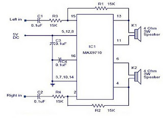
3 Watt stereo amplifier circuit using MAX 7910 IC. The MAX9710 a stereo audio power amplifier IC capable of delivering 3Watts of out put to 4 Ohm loads. MAX9710 can be operated from a single 4.5V to 5.5V power supply , makes it ideal for hand held applications.The IC for 3 Watt stereo amplifier circuit also features thermal overload protection.


Circuit Schematics 3 Watt  Stereo Amplifier MAX 7910 
3 Watt stereo amplifier circuit
3 Watt stereo amplifier circuit 

This 3 Watt stereo amplifier circuit  is suitable for small power audio devices such as radio sets and portable CD players. 5 V DC power supply is used for powering the 3 Watt stereo amplifier circuit. 6V battery with an IN 4007 diode series to the positive terminal of it can also be used instead of 5 V DC supply. The 3 Watt stereo amplifier circuit will get a supply voltage approximately 5 V after 0.7 V voltage drop across diode.

Read More..