Showing posts with label 20w. Show all posts
Showing posts with label 20w. Show all posts
Friday, October 3, 2014
20W Bridge Amplifier with TDA2005
TDA2005 is a 20W amplifier is a bridge to the car radio. The TDA 2005 is ClassB dual audio power amplifier in MULTIWATT) package specifically designed for car radio applications: power booster amplifiers are easily designed with this device that provides a high current capability (up to 3.5 A) and that can handle very low impedance loads (up to 1.6 W).
TDA2005M is designed to bridge TDA2005S applications for music application. With TDA 2005S can build a 2 x 10watt stereo amplifier circuit 2 x 2Ω speakers with 10% distortion.
TDA 2005 maximum ratings
Operating Supply Voltage 18 V
DC Supply Voltage 28 V
Peak Supply Voltage (for 50 ms) 40 V
Output Peak Current (non repetitive t = 0.1 ms) 4.5 A
Output Peak Current (repetitive f . 10 Hz) 3.5 A
Power Dissipation at Tcase = 60 °C 30 W
Storage and Junction Temperature – 40 to 150 °C

Tuesday, September 2, 2014
LM1875 AUDIO AMPLIFIER 20W
LM1875general description:
The LM1875 is a monolithic power amplifier offering very low distortion and high quality performance for consumer audio applications. The LM1875 delivers 20 watts into a 4Ω or 8Ω load on ±25V supplies. Using an 8Ω load and ±30V supplies, over 30 watts of power may be delivered. The amplifier is designed to operate with a minimum of external components. Device overload protection consists of both internal current limit and thermal shutdown.The LM1875 design takes advantage of advanced circuit techniques and processing to achieve extremely low distortion levels even at high output power levels. Other outstanding features include high gain, fast slew rate and a wide power bandwidth, large output voltage swing, high current capability, and a very wide supply range. The amplifier is internally compensated and stable for gains of 10 or greater.
LM1875 amplifier circuit:
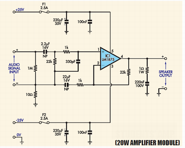
LM1875 power supply diagram:

LM1875 pcb layout:

LM1875 project review:

Monday, September 1, 2014
20W 40W Fluorescent Lamp Inverter Wiring diagram Schematic
This is certainly a low-cost 20W/40W fluorescent lamp inverter schema project. Even so the maximum effective would be to make use of a 40 watt tube (or two 20 watt tubes in series). It is a schema you may put collectively from junk box parts or assemble from a kit. It certainly is quite easy to construct and no need printed schema board. The transformer is hand-wound on a ferrite rod (from an old transistor radio) and the winding wire could be salvaged from an old transformer. We’re intentionally maintaining bills down to confirm how cheaply it could be put together.
20W/40W Fluorescent Lamp Inverter Schematic
Dependant upon your stock of components, the cost could vary from $3.00 to about $15.00 and in case the wires from the transformer are soldered to the ends of the tube(s), you are able to make a free-standing light that can be set-up in the garden to light up a dark place without having the worry of operating 240v wiring. The cost of powering the schema is about 22 watts and this will make the same light output as a 60 watt globe.
Using a regular fluoro operating on the 240v mains, a ballast (or choke) is required in series with the tube to limit the current after the tube has “struck”. This ballast dissipates about 10-20 watts for a 20 watt tube and lowers the effectiveness of this schema. In case the ballast is replaced with an electronic schema and high-frequency transformer, the losses are lower than 5 watts. In addition, if we tend not to drive the tube as tough as the 240v type we are able to get even better effectiveness.
Using a regular fluoro operating on the 240v mains, a ballast (or choke) is required in series with the tube to limit the current after the tube has “struck”. This ballast dissipates about 10-20 watts for a 20 watt tube and lowers the effectiveness of this schema. In case the ballast is replaced with an electronic schema and high-frequency transformer, the losses are lower than 5 watts. In addition, if we tend not to drive the tube as tough as the 240v type we are able to get even better effectiveness.
Parts List:
1 – 2R2 1/4watt (for testing)
1 – 47R 1/4watt
1 – 180R 1watt
1 – 47k
1 – 100k mini rim pot
1 – 100ngreencap
1 – 100u 16v electrolytic
1 – BC338 transistor
1 – TIP 3055 transistor
1 – on/off switch
1 – 12mm bolt and nut for transistor
1 – heat-sink 5cm x 10cm
1 – ferrite rod 10mm dia x 8m long
1 – 30m winding wire .28mm dia
1 – 4m winding wire .61 mm dia (wire diameters are NOT critical)
1 – insulation tape either sticky tape or masking tape
1 – interlayer insulation – paper
PCB Kit Design:

Sunday, August 31, 2014
20W BRIDGE AMPLIFIER FOR CAR RADIO
Features:
- COMPACT HEPTAWATT PACKAGE
- FEW EXTERNAL COMPONENTS
- OUTPUT PROTECTED AGAINST SHORT
- CIRCUITS TO GROUND AND ACROSS LOAD
- DUMP TRANSIENT
- THERMAL SHUTDOWN
- LOUDSPEAKERPROTECTION
- HIGH CURRENT CAPABILITY
- LOW DISTORTION/LOW NOISE
Circuit Diagram:
 |
| 20W BRIDGE AMPLIFIER FOR CAR RADIO |
Subscribe to:
Posts (Atom)
