Monday, November 3, 2014
Soldering Iron Inverter
The complementary outputs from the collectors of transistors Q1 and Q2 are fed to pnp Darlington driver stages formed by transistor pairs Q3-Q5 and Q4-Q6 (utilising BC558 and BD140). The outputs from the drivers are fed to transistors Q7 and Q8 (each 2N3055) connected for push-pull operation. Use suitable heat-sinks for transistors Q5 through Q8. A 230V AC primary to 12V-0-12V, 4.5A secondary transformer (T1) is used.
Connect the battery and transformer with suitable current-carrying wires. On the front panel of the box, fit power switch S1 and a 3-pin socket for connecting the soldering iron. Note that the ratings of the battery, transistors T7 and T8, and transformer may vary as these all depend on the load (soldering iron).

Wednesday, September 24, 2014
Power Inverter 1000 Watt by Mosfet

This power inverter circuit will provide a very stable “Square Wave” Output Voltage. Frequency of operation is determined by a pot and is normally set to 60 Hz. Various “off the shelf” transformers can be used. Or Custom wind your own for best results.

The Power leads must be heavy enough wire to handle this High Current Draw! appropriate Heat Sinks Should be used on the RFP50N06 Fets. These Fets are rated at 50 Amps and 60 Volts. Other types ofMosfets can be substituted if you wish.

Note
There ARE Limitations! I have had numerous requests for an Inverter for 1000 watts and Even MORE. Sorry I Don’t feel this is Practical. At 1000 Watts and operating from a 12 Volt Source, the Input Current will be close to 100 AMPS. That would Require a HUGH Size of a Primary Wire.
Tuesday, September 9, 2014
Positive to Negative Voltage Inverter
Schematic diagram:

Component list:
| Part | Total Qty. | Description | |
| R1 | 1 | 24K 1/4 Watt Resistor | |
| R2 | 1 | 56K 1/4 Watt Resistor | |
| C1 | 1 | 3300pF 25V Ceramic Capacitor | |
| C2 | 1 | 47uF 25V Electrolytic Capacitor | |
| C3 | 1 | 10uF 25V Electrolytic Capacitor | |
| D1, D2 | 2 | 1N4148 Silicon Diode | |
| U1 | 1 | 555 Timer | |
| MISC | 1 | Wire, Board |
Notes:
- V+ can be anywhere from 4 to 16V. -V is one volt less than V+. So for -12V output, use +13V input. The maximum current output of the schema is about 280mA, more than enough for a few op amps.
- For better regulation, a 79LOxx series regulator can be used.
- A zener diode may also be used to regulate the output voltage.
Thursday, September 4, 2014
Push Pull Square wave DC to AC Inverter
Monday, September 1, 2014
20W 40W Fluorescent Lamp Inverter Wiring diagram Schematic
Using a regular fluoro operating on the 240v mains, a ballast (or choke) is required in series with the tube to limit the current after the tube has “struck”. This ballast dissipates about 10-20 watts for a 20 watt tube and lowers the effectiveness of this schema. In case the ballast is replaced with an electronic schema and high-frequency transformer, the losses are lower than 5 watts. In addition, if we tend not to drive the tube as tough as the 240v type we are able to get even better effectiveness.
Parts List:
1 – 2R2 1/4watt (for testing)
1 – 47R 1/4watt
1 – 180R 1watt
1 – 47k
1 – 100k mini rim pot
1 – 100ngreencap
1 – 100u 16v electrolytic
1 – BC338 transistor
1 – TIP 3055 transistor
1 – on/off switch
1 – 12mm bolt and nut for transistor
1 – heat-sink 5cm x 10cm
1 – ferrite rod 10mm dia x 8m long
1 – 30m winding wire .28mm dia
1 – 4m winding wire .61 mm dia (wire diameters are NOT critical)
1 – insulation tape either sticky tape or masking tape
1 – interlayer insulation – paper
PCB Kit Design:

Wednesday, August 27, 2014
Semi Low Power Inverter Wiring diagram Schematic
Saturday, August 16, 2014
Inverter 5000 Watt PWM
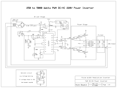 |
| Schematic Inverter 5000W with PWM (Pulse Width Modulator) |
 |
| Layout PCB Inverter 5000W with PWM (Pulse Width Modulator) |
below is the output power settings that can be issued by this inverter:
DC voltage and Transformer "T2" winding recommendation:
Winding Power Supply
12VDC 750W P: 24V "12-0-12" / S: 220V
1500W 24VDC P: 48V "24-0-24" / S: 220V
2250w 36VDC P: 72V "36-0-36" / S: 220V
3000w 48VDC P: 96V "48-0-48" / S: 220V
3750w 60VDC P: 120V "60-0-60" / S: 220V
4500w 72VDC P: 144V "72-0-72" / S: 220V
5250w 84VDC P: 168V "84-0-84" / S: 220V
Transformer used is the transformer CT
R1 serves to regulate the voltage to 220v inverter
R2 serves to regulate the inverter output frequency of 50 or 60 Hz (as appropriate)
Friday, August 15, 2014
12V to 230V Inverter Wiring diagram Schematic


# Be careful when you deal with 230V
# This is not a suitable schema for kids so dont try to test this because 230V is dangerous
