Showing posts with label dc. Show all posts
Showing posts with label dc. Show all posts
Tuesday, November 18, 2014
DC DC Converter 12V to 24V
This simple circuit is a DC-DC converter that converting up 12V source to a 24V. It can be used to run radios, small lights, relays, horns and other 24V accessories from a 12V vehicle with a maximum draw of about 800mA.
This DC-DC Converter can be used to charge one 12V battery from another, or step up the voltage just enough to provide necessary overhead for a 12V linear regulator. Using one op-amp as a squarewave oscillator to ring an inductor and another op-amp in a feedback loop, it wont drift around under varying loads, providing a stable 24V source for many applications. With a wide adjustment in output this circuit has many uses.
Parts List
R1-R4,R7-R8 100K 1/4W Resistor
R5 470 Ohm 1/2W Resistor
R6 10K Linear Pot
C1 0.01uF Mylar Capacitor
C2 0.1uF Ceramic Disc Capacitor
C3 470uF 63V Electrolytic Capacitor
D1 1N4004 Rectifier Diode
D2 BY229-400 Fast Recovery Diode See Notes
Q1 BC337 NPN Power Transistor
U1 LM358 Dual Op Amp IC
L1 See Notes
MISC Board, Wire, Socket For U1, Case, Knob For R6, Heatsink for Q1
DC- DC Converter Notes
1. R6 sets the output voltage. This can be calculated by Vout = 12 x (R8/(R8+R7)) x (R6B/R6A).
2. L1 is made by winding 60 turns of 0.63MM magnet wire on a toroidial core measuring 15MM (OD) by 8MM (ID) by 6MM (H).
3. D2 can be any fast recovery diode rated at greater then 100V at 5A. It is very important that the diode be fast recovery and not a standard rectifier.4. Q1 will need a heatsink.

Monday, November 17, 2014
12V to 20V DC converter
DC To DC Converter circuit used to be an alter tegngan voltage DC to DC with different concepts. DC to DC converter circuit +12 V to + /-20V is working to change the battery voltage from 12V DC to 20V DC voltage symmetrical. DC to DC converter circuit is often applied to the power amplifier udio on car audio systems. DC to DC converter circuit uses a TL494 IC as power plsa for the converter. TL494 IC is a PWM controller with an adjustable frequency from 40-60Hz through a potentiometer. Then from the TL494 PWM signal is given to the driver MOSFET inverter TPS2811P to be given to the power inverter with 2 units of MOSFET transistors. Circuit details can be seen in the figure following the DC to DC converter.
DC To DC converter circuit +12 V To + / - 20V
![+12V]()
List Components DC To DC Converter +12 V To + / - 20V
R1, R2 = 10
R3, R4, R6, R7 = 1k
R5 = 22k
R8 = 4.7k
R9 = 100k
C1, C2 = 10000uF
C3, C6 = 47 u
C4 = 10U
C5, C7, C14 = 100n
C8, C9 = 4700u
C12 = 1N
C13 = 2.2u
U1 = TL494
U2 = TPS2811P
Q1, Q2 = FDB045AN
D1-D4 = 1N5822
D5 = 1N4148
FU1 = 10A
L1 = 10U
L2 = ferrite BEAD
RV1 = 2.2k
RV2 = 24k
T1 = TRAN-3P3S
DC To DC converter circuit +12 V To + / - 20V is capable of supplying up to 100W and can power supplying currents up to 3A. In making DC To DC Converter +12 V To + / - 20V has to be careful and cautious because there are parts of DC To DC Converter +12 V To + / - 20V in the form of an AC circuit.
Read More..
DC To DC converter circuit +12 V To + / - 20V
List Components DC To DC Converter +12 V To + / - 20V
R1, R2 = 10
R3, R4, R6, R7 = 1k
R5 = 22k
R8 = 4.7k
R9 = 100k
C1, C2 = 10000uF
C3, C6 = 47 u
C4 = 10U
C5, C7, C14 = 100n
C8, C9 = 4700u
C12 = 1N
C13 = 2.2u
U1 = TL494
U2 = TPS2811P
Q1, Q2 = FDB045AN
D1-D4 = 1N5822
D5 = 1N4148
FU1 = 10A
L1 = 10U
L2 = ferrite BEAD
RV1 = 2.2k
RV2 = 24k
T1 = TRAN-3P3S
DC To DC converter circuit +12 V To + / - 20V is capable of supplying up to 100W and can power supplying currents up to 3A. In making DC To DC Converter +12 V To + / - 20V has to be careful and cautious because there are parts of DC To DC Converter +12 V To + / - 20V in the form of an AC circuit.
Sunday, October 5, 2014
DC Power Supply Dual rail Variable Circuit
DC Power Supply Dual-rail Variable Circuit
* The circuit can be placed into the existing Variable DC Power Supply metal cabinet.
* Q1 and Q2 must be mounted on heatsinks. Usually, bolting them to the metal case (through insulating washers etc.) proved effective.
* The full ±15V output can be achieved only if the secondary winding of the supply Transformer used in the Variable DC Power Supply is rated at 48V minimum (center tapped).
* When using this circuit, please set the Current-limit control (P1) of the Variable DC Power Supply to any value comprised in the 50mA - 1A range but not higher.
* The second Op-amp (IC1B) contained in the LM358 chip was not used, but its input pins were tied to the negative supply and the output was left open.
* Q1 and Q2 must be mounted on heatsinks. Usually, bolting them to the metal case (through insulating washers etc.) proved effective.
* The full ±15V output can be achieved only if the secondary winding of the supply Transformer used in the Variable DC Power Supply is rated at 48V minimum (center tapped).
* When using this circuit, please set the Current-limit control (P1) of the Variable DC Power Supply to any value comprised in the 50mA - 1A range but not higher.
* The second Op-amp (IC1B) contained in the LM358 chip was not used, but its input pins were tied to the negative supply and the output was left open.
DC Power Supply Dual-rail Variable Part list:
R1 = 4.7K-1/2W
R1 = 4.7K-1/2W
C1 = 100nF-63V
C2 = 220µF-25V
C3 = 220µF-25V
C4 = 100nF-63V
C5 = 100nF-63V
Q1 = BD437
Q2 = BD438
IC1 = LM358
Thursday, September 4, 2014
Push Pull Square wave DC to AC Inverter
This Push-Pull Square wave DC-to-AC Inverter uses inverter gates for the oscillator part, then use one of the gate to invert the produced square wave signal. With push pull operation, the primary coil of the transformer is driven with alternate direction, with the help of H bridge of power transistors (MOSFET) 2SJ471 and 2SK2956.Using the transformer shown in the schematic diagram, this inverter schema produce 110VAC from 12VDC input, but you can easily modify this schema to produce 220VAC by replacing the transformer with 220V type (12V-220V) of the same amperage (10A).
Push-Pull Square wave DC-to-AC Inverter
Wednesday, August 27, 2014
Suitable AC DC Wiring diagram Schematic
This schema is simple, but very useful as well as simple and inexpensive. Its use is simple, when the positive (red) is connected to a positive voltage DC and the black lead on the negative, the red LED lights. Reversing polarities the Green LED lights. Connecting the ends to an AC source both LEDs will light. The lamp current is limited to 40mA LEDs @ 220V AC and its filament is illuminated with approximately 30V, shining more intensely with increasing tension. Therefore, due to the behavior of the filament, any voltage in the range of 1.8 to 230 can be detected without changing component values.
Suitable AC DC Circuit Diagram

D1 = 3 mm or 5. red LED
D2 = 3 mm or 5. green LED
LP = 1220V 6W NEON
Wednesday, August 13, 2014
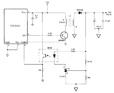
Build a Isolated Dc Dc Converter Wiring diagram Schematic
This Isolated Dc-Dc Converter Circuit Diagram, a TU31 shunt regulator is used to sense the output voltage. The TU31 drives the LED of a 4N28 optocoupler which provides feedback to the MAX641 while maintaining isolation between the input, +12 V, andJhe output, +15 V. ln this Isolated Dc-Dc Converter Circuit Diagram, the +15 V output is fully regulated with respect to both line and load changes.
Isolated Dc-Dc Converter Circuit Diagram
Subscribe to:
Posts (Atom)
