Showing posts with label supply. Show all posts
Showing posts with label supply. Show all posts
Monday, November 17, 2014
Power Supply EL 34
Power supply for EL-34 tube is specially designed for the purposes of power supply at the push-pull amplifier with EL-34 tube as in article 35 Watt Tube Power Amplifier Push Pull before. Power supply for EL-34 tube amplifier is made with transformers CT and 2 pieces diode as rectifier. Mechanical filters are applied in the power supply uses 3 levels. Power supply for tube power amplifier can deliver output voltages +220 VDC. Circuit details can be seen in the following figure.

The above power supply circuit has a high output voltage so that need to be considered in the manufacture and perakitanya because electricity can tesengat (stun). Power Supply For Tube Power Amplifier With Diode EL-34 was created specifically for the power amplifier tube push pull EL-34.

Monday, October 27, 2014
Type of UPS Uninterruptible Power Supply
UPS design of the model is divided into several types that produce different performance characteristics:
A. Standby
2. Line Interactive
3. Double Conversion On-Line
4. Delta Conversion On-Line
Standby UPS typesThis type is commonly used by home users for the Presidency with their PC. UPS to be able to do this type of filtration against power failures and flow management, in addition to design efficient, small size and inexpensive.
Line Interactive UPS types
fine.
UPS has an inverter is always connected to the output of the UPS system to convert the power from batteries into AC. In normal circumstances, the Inverter will perform battery charging. While in a state of power outages, Transfer Switch will close and drain power from the batteries to the UPS output. Position that is always connected to the inverter output filter provides additional power. This makes the type of UPS is widely used for server and electrical conditions are not too good.
Double Conversion type UPS On-Line
This type is most common for UPS with power more than 10kVA. These types have in common with the type of Standby. Only this type has a power source located on the inverter, not the AC power source. In this type, the main electricity supply interruption will not trigger a transfer switch for the incoming AC power to the central input to charge the batteries that provide power to the Inverter located at the output. Therefore, when the AC power is disconnected, the flow of energy will be transferred immediately without taking a break when the transfer occurs. This type of UPS above shows the performance of the average. Can be said of this type of approach the ideal of a UPS, unfortunately this type of heat is high enough.
UPS type Delta Conversion On-Line
Almost the same as the Double Conversion type, type Delta used to always supply voltage Inverter. When the power supply is interrupted, this type do the same with Double Conversion type. Delta Conversion has two functions, the first is to control the input power characteristics. While the second function is to control the input current to direct the process of charging the battery system. The thing to remember is to minimize this type of energy is wasted. In addition, it has a high compatibility to various types of generators and reduce the need for the use of cables.
Sunday, October 19, 2014
ca3140 5V 13V power supply variable regulated

This be power supply variable regulator circuit, since 5V to 13V that current about 1A. By use IC LM7805 (3-Terminal 1A Positive Voltage Regulator) perform maintain one’s position voltage, be stable that 5V. And have op-amp IC number CA3140 , help fine decorate voltage go out can modify 5V to 13V from get, by use VR1 in fining decorates. It takes current from output feed come back still a pin GND of LM7805 control the level voltage get efficiently better using resistor R1 only. See little detail in the circuit.
Saturday, October 18, 2014
IC 723 TIP41 Laboratory Power Supply Variable voltage

1.2V – 12V with regulated current limiter through resistors
Person see the website wants DC Volt adjustable Regulate 1.2V to 12V current 1-2A sizes at the first stage me think will choose the circuit that use IC LM317. But he tells have IC LM723 the many. Then of this circuit better which this easy circuit, use integrated number this circuit. And still use number transistor TIP41 0R TIP31 help enlarge current get about 1-2A fine VR1 for choose Volt follow want. The detail is other can see in the circuit has and original website http://www.elektroda.net/warsztatowe/zasilaczelabor.html
Thursday, October 16, 2014
Simple 0 50V 2A Bench Power Supply Circuit Diagram
I use the lm10 IC because it has a reference voltage and that’s useful for dc power supply. With two ICs can take different output voltage and amperage. This circuit is protected from short circuit.P2 is for controlling the current at the range of 0-2A. Stabilize the output voltage with R4 on negative pin on op-amp and with R2 & P1 on positive pin.
0-50V 2A Bench Power Supply Circuit Diagram

Op-amp output controls T1 that not let ripple of voltage.T1 increase or decrease ampere of R6 and control the voltage of T5 & T4. Pin 1 is the reference voltage and reference voltage is losing some voltage on R1 that has 100uA . This current passes through P1 too.
Vlose p1=100uA*Rp1
Vlose p1=100uA*Rp1
This lose voltage regulate output voltage rate of output current is compare between reference voltage of P3 and lose voltage on R11.T3 is protecting short circuit with R11. For reduce out put voltage to 0v should parallel one resistor 470 ohm in out put. Minimum voltage is 0.4v. The maximum output voltage is fixed with R1b and should not become over of 50v. Therefore your transformer should give 36V, 3A with 4700uF capacitor. T6, T5, T7 need heatsilk.
R1a = 2,2 K
R1b = read the text
R2 = 10 K
R3, R7 = 3.3 k
R4 = 390 Ohm
R5 = 47 K
R6 = 3.3 K 1Watt
R8 = 180 Ohm
R9, R10 = 0.47 Ohm 3Watt
R11 = 0.075 Ohm 2Watt
R12 = 470 Ohm
P1 = 500K liner potentiometer
P2 = 4.7 K potentiometer
P3 = 10 K potentiometer
C1 = 1nF
C2 = 10nF
C3 = 22nF
C4 = 47mF 63v electrolytic
C5 = 4700mF 80v electrolytic
T1, T2 = BC161
T3, T4 = BD141
T5 = BD241
T6, T7 = 2V3055
D1, D2 = 1N4148
D3, D4 = 1N4001
IC1, IC2 = LM10C
R1b = read the text
R2 = 10 K
R3, R7 = 3.3 k
R4 = 390 Ohm
R5 = 47 K
R6 = 3.3 K 1Watt
R8 = 180 Ohm
R9, R10 = 0.47 Ohm 3Watt
R11 = 0.075 Ohm 2Watt
R12 = 470 Ohm
P1 = 500K liner potentiometer
P2 = 4.7 K potentiometer
P3 = 10 K potentiometer
C1 = 1nF
C2 = 10nF
C3 = 22nF
C4 = 47mF 63v electrolytic
C5 = 4700mF 80v electrolytic
T1, T2 = BC161
T3, T4 = BD141
T5 = BD241
T6, T7 = 2V3055
D1, D2 = 1N4148
D3, D4 = 1N4001
IC1, IC2 = LM10C
Sunday, October 5, 2014
DC Power Supply Dual rail Variable Circuit
DC Power Supply Dual-rail Variable Circuit
* The circuit can be placed into the existing Variable DC Power Supply metal cabinet.
* Q1 and Q2 must be mounted on heatsinks. Usually, bolting them to the metal case (through insulating washers etc.) proved effective.
* The full ±15V output can be achieved only if the secondary winding of the supply Transformer used in the Variable DC Power Supply is rated at 48V minimum (center tapped).
* When using this circuit, please set the Current-limit control (P1) of the Variable DC Power Supply to any value comprised in the 50mA - 1A range but not higher.
* The second Op-amp (IC1B) contained in the LM358 chip was not used, but its input pins were tied to the negative supply and the output was left open.
* Q1 and Q2 must be mounted on heatsinks. Usually, bolting them to the metal case (through insulating washers etc.) proved effective.
* The full ±15V output can be achieved only if the secondary winding of the supply Transformer used in the Variable DC Power Supply is rated at 48V minimum (center tapped).
* When using this circuit, please set the Current-limit control (P1) of the Variable DC Power Supply to any value comprised in the 50mA - 1A range but not higher.
* The second Op-amp (IC1B) contained in the LM358 chip was not used, but its input pins were tied to the negative supply and the output was left open.
DC Power Supply Dual-rail Variable Part list:
R1 = 4.7K-1/2W
R1 = 4.7K-1/2W
C1 = 100nF-63V
C2 = 220µF-25V
C3 = 220µF-25V
C4 = 100nF-63V
C5 = 100nF-63V
Q1 = BD437
Q2 = BD438
IC1 = LM358
Monday, September 8, 2014
Build a Power Supply Variable 1 3V 12 2V 1A Wiring diagram Schematic
Build a Power Supply Variable 1.3V - 12.2V 1A Circuit Diagram. In this schema R2 to set the output voltage. The maximum current is determined by R3, over-current protection schema inside the LM723 to detect the voltage on R3, if it reaches 0.65 V, the voltage output will be off her. So the current through R3 can not exceed 0.65 / R3 although output short-schema in his.
Power Supply Variable 1.3V - 12.2V 1A Circuit Diagram
C3 and C4 are ceramic capacitors, as much as possible directly soldered to the PCB, this is because the LM723 is prone to oscillation that is not cool.
LM723 works with 9.5V input voltage to 40 V DC and the LM723 can generate its own current of 150mA when the output voltage is not more than 6-7V under input voltage.
Specifications:
Output (value estimated):
Vmin = (R4 + R5) / (R5 * 1.3)
Vmax = (7.15 / R5) * (R4 + R5)
Imax = 0.65/R3
Max. Power on R3: 0.42/R3
Min. DC Input Voltage (pin 12 to pin 7): Vmax + 5
Parts List:
B1 40V/2.5A
C1 2200uF (3300uF even better)
C2 4.7uF
C3 100nF
C4 1NF
C5 330nF
C6 100uF
Green LED D1
D2 1N4003
F1 0.2A F
F2 2A M
IC1 LM723 (in a DIL14 plastic package)
R1 1k
R2 Pot. 5k
R3 0.56R/2W
R4 3.3k
R5 4.7k
S1 250V/1A
T1 2N3055 on a heatsink 5K / W
TR1 220V/17V/1.5
Friday, September 5, 2014
How a Power Supply Works
This article describes in easy terms the operation of a Basic Power Supply unit of the kind used with telecommunications instrumentality (switchboards, physics house exchange systems, plan-sets, etc).
The term power provide is a lot of normally abbreviated to PSU, this may be wont to electronic device to be ready to work. So, the facility supply unit is use to come up with a voltage that may be supply in associate device in accordance with the wants of the mains voltage from that device. Telecommunications instrumentality and notebook is meant to control on lower voltages than electrics domestic Mains voltage. So as to scale back this voltage a PSU (Power Supply Unit) is employed.
To provide a useable low voltage the PSU desires a number of criteria :
- Scale back the Mains 220V AC (Alternating current) voltage to a lower level, examples 5VDC.
- Convert this Lower Voltage from AC to DC (Direct current), this use Diode and Capacitor to converting.
- Regulate the DC output to make amends for varied load (current demand)
- Give Protection against excessive input/output voltages, it use Regulator supply system.
1. Reduction of AC Mains
This is achieved by employing a device called a electrical device associate magnetic attraction device consisting of associate ferric email iron core that incorporates a sizable amount of turns of wire wound around it, called the first Winding. The ends of those turns of wire being connected to the input voltage, in this case Mains AC.
A second range of turns of wire-protected measure wound round the coil, this set being called the coil.
The distinction between the quantity of turns provides simplest way of reducing a high AC voltage to a lower one.
2. Conversion of AC to DC
To convert our currently low AC voltage to DC we tend to use a Rectifier Diode connected to the coil.
This is a chemical element diode, that has operation analogous to a bicycle tyre valve (as the valve solely permits air to flow into the tyre, the diode solely permits current to flow in one direction).
As our low AC voltage are going to be functioning at a frequency of 50 - 60Hz (Mains AC frequency) its fascinating to scale back the inherent hum on this to a lower level.
This is achieved by a method called Smoothing (filtering out the bumps within the AC).
A simple thanks to scale back the hum is to use Full Wave Rectification.
Today this is often typically done by four diodes during a bridge configuration called a Bridge Rectifier. (This will be four individual diodes or an infatuated self contained package)
3. Give Regulation of Outp ut Voltage, [SEE next article from about REGULATOR.
The capacitance could be a device capable of storing energy the quantity of energy and therefore the time it remains hold on counting on the worth. In a straightforward PSU the simplest thanks to give regulation to make amends for varied load conditions is to use a try of comparatively high price Electrolytic Capacitors.
Their values during this case being within the between of 470uF to 4700uF counting on the applying and therefore the quantity of current needed from the output of the unit. One of these capacitors and Electrolyte Capacitors is connected across the DC output of the rectifier diode(s) or bridge, this electrical device conjointly providing an additional degree of smoothing the output wave.
The second electrical device is connected via an occasional price, medium to high electric power resistance, that assists in limiting this demand.
4. Protection against excessive voltages
In a straightforward PSU the simplest thanks to do that is by providing fuses at the input to the electrical device, usually within the live facet of the mains provide, conjointly at the DC outputs.
In the event of associate excessive input voltage, or excessive current being drawn from the output, one amongst these fuses ought to commonly blow protective the PSU and therefore the instrumentality connected to that.
The electrical device might also be fitted with an indoor or external thermal fuse, which can open if the electrical device becomes hot thanks to the said conditions.
| How a Power Supply Works |
Thursday, September 4, 2014
Constructing a Universal Power Supply using LM317 Rise
This is a basic, Universal Power Supply voltage regulator schema using an LM317, 3-terminal regulator in a TO-220package. The Universal Power Supply output voltage can be set to anywhere in the range one.5V to 30V by selecting resistances. By using a potentiometer, R2, as of the resistors you can dial up the output voltage wanted. Either AC or DC input can be supplied to the PCB by a socket or terminal block. Connection can be either way around. This is because they have provided a bridge rectifier on board. The input DC voltage to the regulator must be at least two.5V above the necessary output voltage. An off/on switch is provided.
For lots of applications (say 12V at 60mA) a heat sink wont be required. The LM317 will provide slightly higher output voltages than 30 volts. However, for most hobbyists over 30V wont be needed. So to make a small PCB they have used some electrolytic capacitors rated to 35 volts. To be safe for continuous operation the maximum input DC voltage to the regulator ought to not be over 33V. With a two.5V to three.0V drop across the regulator this will give a regulated output of 30V. You can draw up to one.5A from the LM317. In case you need higher then use an LM338T rated to 5A.
When outside capacitors are used with any IC regulator it is lovely practice to add protection diodes to prevent the capacitors discharging back in to the regulator in the event of abnormal operating conditions, like a sudden short schema on the input or the output, or a back emf from an inductive load. That is the function of D one and D Two.
The worth of R1 can range anywhere from 120R to 1200R However, diagram from most other sources settle on using either 220R or 250R. They have used 240R or 250R. The voltage drop across R1is one.25V for all values, and this is the key to the design. one.25V is the reference voltage of the regulator. Whatever current flows through R1 also flows through R2, and the sum of the voltage drops across R1 and R2 is the output voltage. (Additional current Id also flows in R2 but it is usually 50uA so is negligible.)
The design formula are:
VOUT = 1.25 (1 + R2/R1) volts, or alternatively
R2/R1 = (VOUT/1.25) - 1
So in case you know VOUT & R1 is 250R then you can calculate R2. In case you find that the 5K potentiometer used forR2 does not give you the degree of fine control over the voltage output range that you need then you can use these formula to fine-tune R1 & R2 to better suited values.

Universal Power Supply Schematic Diagram

Sunday, August 31, 2014
Switch Selected Fixed Voltage Power Supply Wiring diagram Schematic
This Switch Selected Fixed Voltage Power Supply Circuit Diagram can serve as a battery eliminator for various devices (such as tape recorders, small radios, clocks, etc.). Si selects a resistance that is predetermined to provide a preselected output voltage. In this schema, various commonly used supply voltages produced by batteries were chosen, but any voltages up to the rating of Tl (approximately) can be produced by choosing an appropriate resistor. Remember to provide adequate heatsinking for Ul.
Switch Selected Fixed Voltage Power Supply Circuit Diagram
Friday, August 29, 2014
Soft Start For Switching Power Supply
Switching power supply whose output voltage is appreciably lower than its input voltage has an interesting property: the current drawn by it is smaller than its output current. However, the input power (UI) is, of course, greater than the output power. There is another aspect that needs to be watched: when the input voltage at switch-on is too low, the regulator will tend to draw the full current. When the supply cannot cope with this, it fails or the fuse blows. It is, therefore, advisable to disable the regulator at switch-on (via the on/off input). until the relevant capacitor has been charged. When the regulator then starts to draw current, the charging current has already dropped to a level which does not overload the voltage source.
Circuit diagram:
Soft Start Circuit For Switching Power Supply
The schema in the diagram provides an output voltage of 5 V and is supplied by a 24 V source. The regulator need not be disabled until the capacitor is fully charged: when the potential across the capacitor has reached a level of half or more of the input voltage, all is well. This is why the zener diode in the diagram is rated at 15 V. Many regulators produced by National Semiconductor have an integral on/off switch, and this is used in the present schema. The input is intended for TTL signals, and usually consists of a transistor whose base is accessible externally. This means that a higher switching voltage may be applied via a series resistor: the value of this in the present schema is 22 kΩ. When the voltage across the capacitor reaches a level of about 17 V, transistor T1 comes on, whereupon the regulator is enabled.
Source: National Semiconductors
Thursday, August 21, 2014
Power Supply 0 15 Volts Adjustable Output
As my article about Power Supply Circuit 11.8V(12V) is equipped with the scheme, it can only be applied only to one is 12V output voltage only. All equipment that requires 12V Power Supply can use that Power Supply, for example; to turn on the car tape installed in your home without use of batteries.
What if there are your electronic devices that require 5V power supply while you are not there ADAPTER 5V power supply.
This can be overcome by assembling the Power Supply 0 to 15 Volts Adjustable Output.
or called Power supply multifunction.
Lets check scheme
| Power Supply 0 - 15 Volts Adjustable Output. |
The construction of this Power Supply Circuit is incredibly straightforward in such the simplest way that the elements used area unit straightforward to be settled whereas the value is incredibly low cost. With the largest provided current at one A, the output voltage is adjusted for minimal ripple result and stable within the vary of zero V to fifteen V DC. This is often created attainable by the quality electrical device output of one.5 A with a primary voltage of 220 V and secondary voltage of eighteen V. the present is being restricted by the Zener diode D1 with a rating of eighteen V and one.5 W. The linear potentiometer R2 is liable for the regulation of current.
2N3055 – a complementary atomic number 14 Epitaxial-Base planar NPN electronic transistor|electronic transistor|semiconductor device|semiconductor unit|semiconductor} mounted in Jedec TO-3 metal case to be used as power Transistor
Bridge Diode – additionally referred to as bridge rectifier that has four diodes organized in a very bridge configuration wherever the output voltage has identical polarity with either polarity of the input voltage
The Power semiconductor Q1 may be a classic sort that might need to be placed in a very appropriate heatsink to suppress the high temperature reduction throughout the operation of the schema. the warmth dissipation are continuous throughout the presence of the best current. The bridge diode GR1 can offer full wave rectification from the AC input which can additionally convert the incoming electricity (AC) input into electricity (DC) output. One smart feature of the bridge diode is maintaining identical polarity of the output notwithstanding the polarity of the input.
The 15V an influence provide is also accustomed handle home automation system which may be supercharged by twelve V DC. they will be created into power adapter models to support a good form of applications like TFT monitors, transmitter, notebook, camera digital , telecommunications, PSP, routers, stringed instrument Guitar effects, extenders, iPod’s, scanners, CCTV, printers, container players, radios, etc.
Tuesday, August 19, 2014
200W power amplifier complete power supply
This 200W power amplifier circuit using IC STK 4050.
STK 4050 is a power amplifier module is very powerful, because the IC is already a module then only needed a little extra components to build a reliable 200W Power Amplifier. Here is a picture series of Power Amplifier ICs 200W use STK 4050 complete with its power supply

12V fixed voltage power supply circuit diagram
Here this schema diagram is for +12V regulated (fixed voltage) DC power supply. These power supply schema diagram is ideal for an average current requirement of 1Amp. This schema is based on IC LM7812. It is a 3-terminal (+ve) voltage regulator IC. It has short schema protection , thermal overload protection. LM7812 IC is from LM78XX series. The LM78XX series IC is positive voltage regulator IC for different voltage requirements, for example LM7805 IC is made for 5 volt fixed output voltage . There is LM79XX IC series for negative voltage .
Circuit diagram of 12V fixed voltage power supply
A transformer(Tx=Primary 230 Volt, Secondary 12 Volt , 1Amp step down transformer) is used to covert 230V to 12V from mains. Here used a bridge rectifier made by four 1N4007 or 1N4003 diode to convert AC to DC . The filtering capacitor 1000uF,25V is used to reduce the ripple and get a smooth DC voltage. This schema is very easy to build. For good performance input voltage should be greater than 12Volt in pin-1 of IC LM7812. Use a heat sink to IC LM7812 for safeguarding it from overheating.
Saturday, August 16, 2014
Constructing a Universal Power Supply using LM317 Rise
This is a basic, Universal Power Supply voltage regulator schema using an LM317, 3-terminal regulator in a TO-220package. The Universal Power Supply output voltage can be set to anywhere in the range one.5V to 30V by selecting resistances. By using a potentiometer, R2, as of the resistors you can dial up the output voltage wanted. Either AC or DC input can be supplied to the PCB by a socket or terminal block. Connection can be either way around. This is because they have provided a bridge rectifier on board. The input DC voltage to the regulator must be at least two.5V above the necessary output voltage. An off/on switch is provided.
For lots of applications (say 12V at 60mA) a heat sink wont be required. The LM317 will provide slightly higher output voltages than 30 volts. However, for most hobbyists over 30V wont be needed. So to make a small PCB they have used some electrolytic capacitors rated to 35 volts. To be safe for continuous operation the maximum input DC voltage to the regulator ought to not be over 33V. With a two.5V to three.0V drop across the regulator this will give a regulated output of 30V. You can draw up to one.5A from the LM317. In case you need higher then use an LM338T rated to 5A.
When outside capacitors are used with any IC regulator it is lovely practice to add protection diodes to prevent the capacitors discharging back in to the regulator in the event of abnormal operating conditions, like a sudden short schema on the input or the output, or a back emf from an inductive load. That is the function of D one and D Two.
The worth of R1 can range anywhere from 120R to 1200R However, diagram from most other sources settle on using either 220R or 250R. They have used 240R or 250R. The voltage drop across R1is one.25V for all values, and this is the key to the design. one.25V is the reference voltage of the regulator. Whatever current flows through R1 also flows through R2, and the sum of the voltage drops across R1 and R2 is the output voltage. (Additional current Id also flows in R2 but it is usually 50uA so is negligible.)
The design formula are:
VOUT = 1.25 (1 + R2/R1) volts, or alternatively
R2/R1 = (VOUT/1.25) - 1
So in case you know VOUT & R1 is 250R then you can calculate R2. In case you find that the 5K potentiometer used forR2 does not give you the degree of fine control over the voltage output range that you need then you can use these formula to fine-tune R1 & R2 to better suited values.

Universal Power Supply Schematic Diagram
Thursday, August 14, 2014
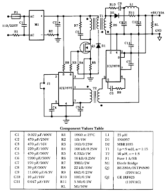
50W Offline Switching Power supply Wiring diagram Schematic
The schematic shows a 50W power supply with a 5-V 10-A output. It is a fly back converter operating in the continuous mode. The schema features a primary side and secondary side controller will full-protection from fault conditions such as over current. After the fault condition has been removed, the power supply will enter the soft-start cycle before recommencing normal operation.
50W Offline Switching Power supply Circuit Diagram
Subscribe to:
Posts (Atom)
